Now we show you how to build an Anderson Mfg. upper receiver and race to the firing line with your very own “I build it myself” AR-15
by Rob Reaser
In the first installment of Build Your Own AR Now!, we mentioned that AR components are finally coming back online after suffering through the empty shelves syndrome of the last year and a half. Anderson Manufacturing, one of the leading producers of OE components for AR manufacturers throughout the country, now has many components in stock as well as complete DIY rifle kits. Since many of you took a keen interest in building your own AR after the chaos of 2020 but couldn’t find the parts to do so, we wanted to take advantage of the current parts availability and walk you through the process of building an AR from scratch (or at least from a box of parts).
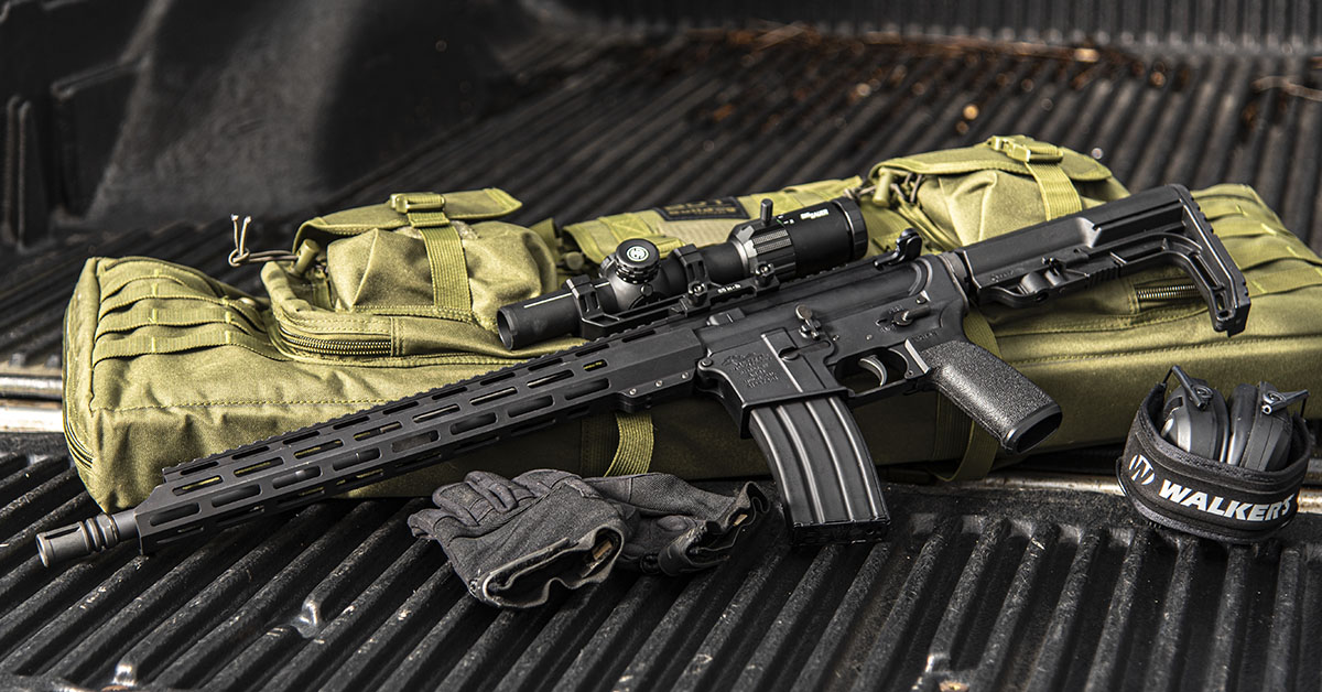
Our first article provided a step-by-step on how to build the first half of an AR-15—the lower receiver. In this installment, we’re going to walk you through the process of building the upper receiver and turning that box o’ parts into a fully functioning rifle. As with the lower receiver build, we’ll be using various tools found in Real Avid’s AR-15 Armorer’s Master Kit. To top it all off, we’ll install Sig Sauer’s Tango-MSR LPVO 1-6x24mm optic to provide the multi-range sighting solution.
Let’s go!
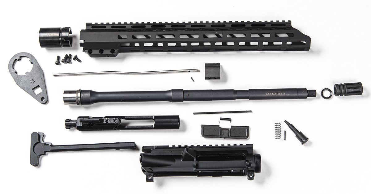
These are the components needed to complete an upper receiver build. Since this kit utilizes a free-float handguard, a proprietary barrel nut is used to secure the barrel and handguard to the receiver. Anderson Manufacturing courteously provides the necessary wrench to tighten the barrel nut. You just need to supply the half-inch-drive foot-pound torque wrench as the nut must be torqued between 30 and 80 ft-lbs.
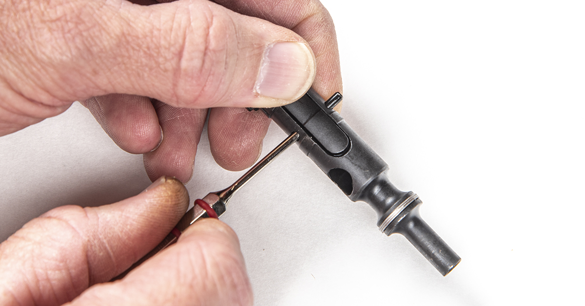
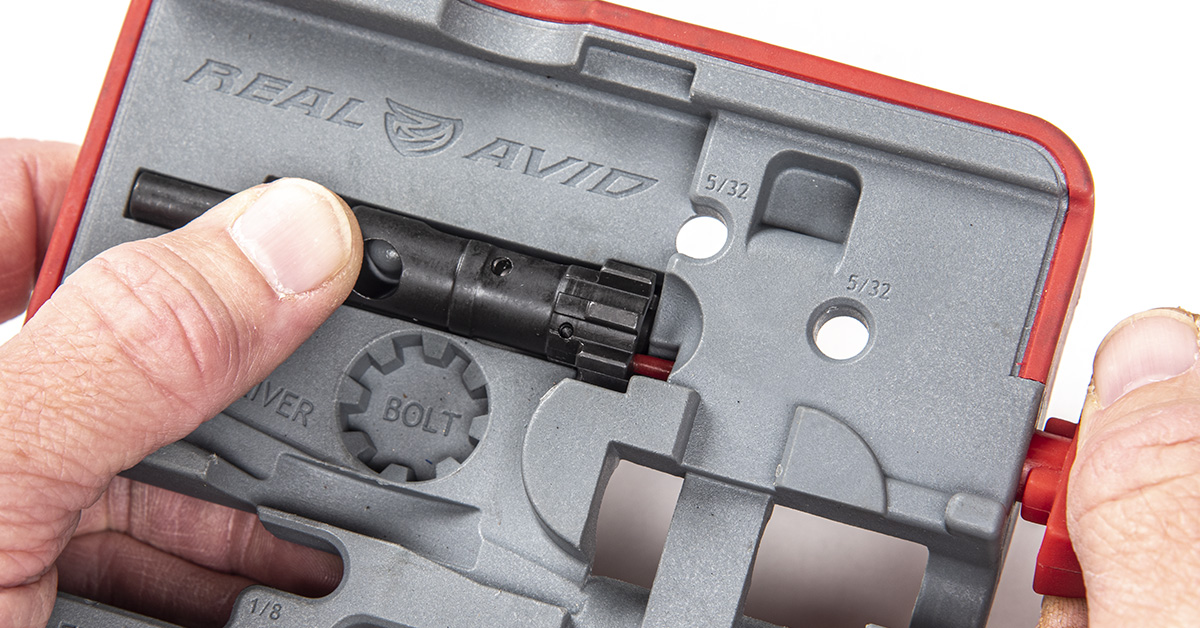
Before anything, it is necessary to ensure the acquired barrel and bolt combination is within SAAMI minimum/maximum for the 5.56/.223 chamber length. Should the combination be out of spec, you’ll want to know that before you assemble the parts. To gauge the chamber length, you must first disassemble the bolt. Begin by removing the extractor retaining pin. Simply depress the extractor and push the pin out with a punch.
With the pin removed, the extractor is lifted out of the bolt.
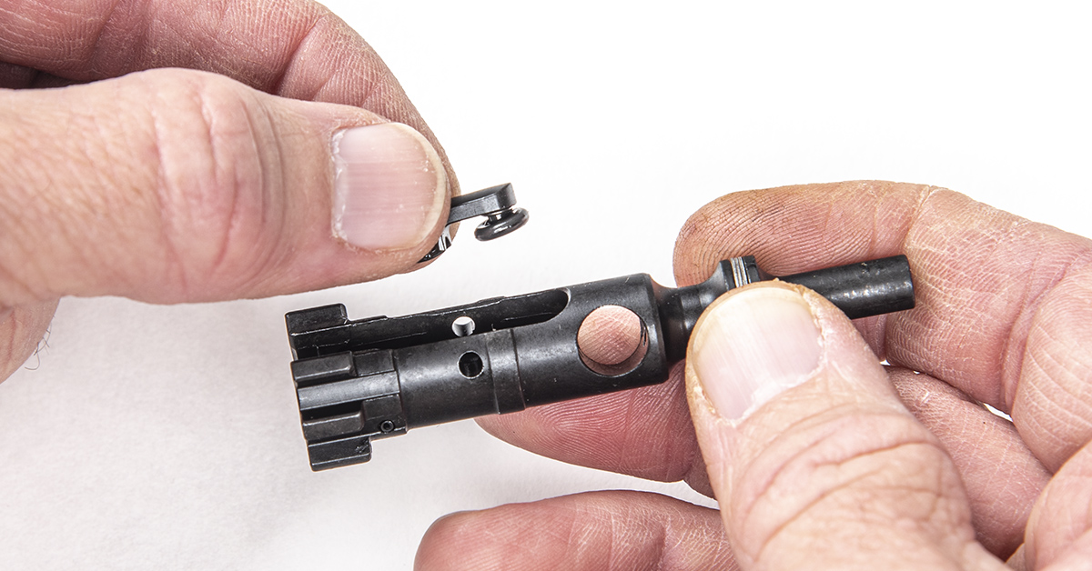
To remove the ejector spring and ejector, it is necessary to depress the ejector. Here, we’re using the Real Avid AR15 Master Bench Block for this task.
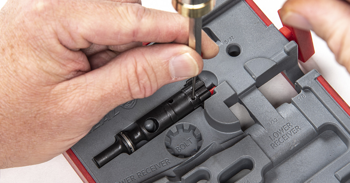
With the ejector pressed into the bolt face, tap out the ejector retaining pin with a roll pin punch.
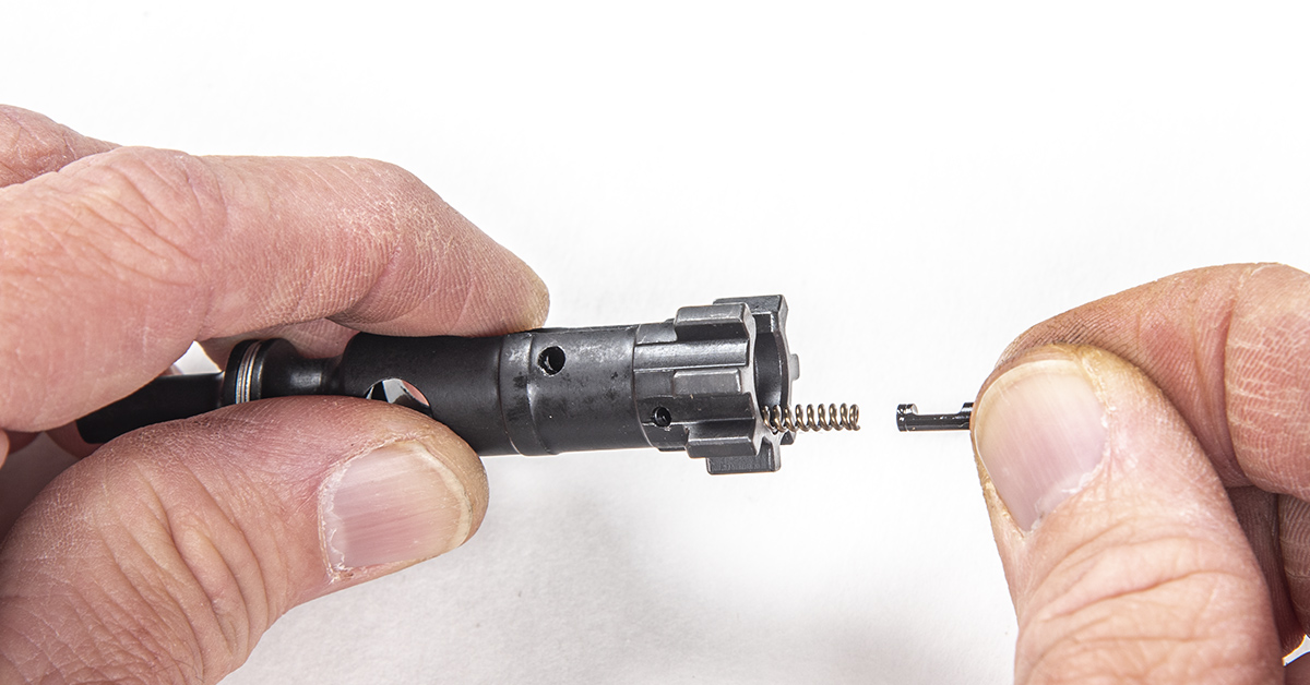
Remove the ejector spring and ejector from the bolt, noting the orientation of the ejector. NOTE: We’ll not cover it here, but bolt reassembly is the reverse of disassembly.
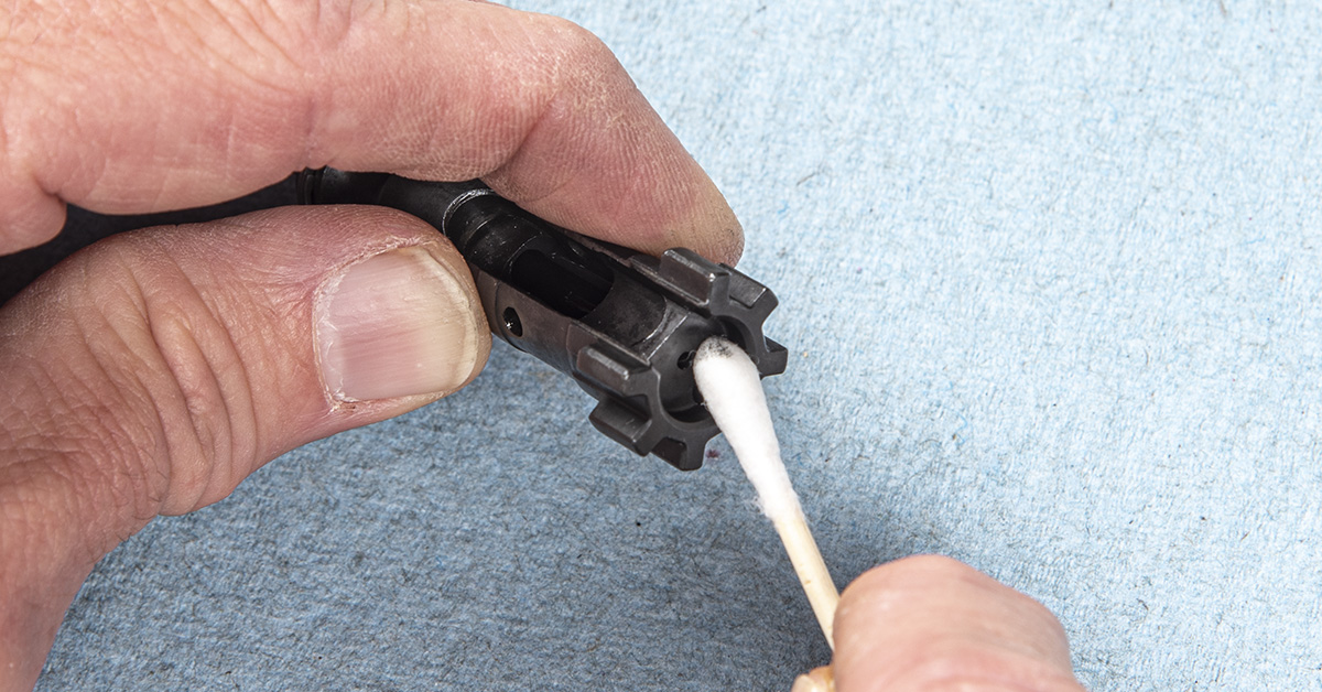
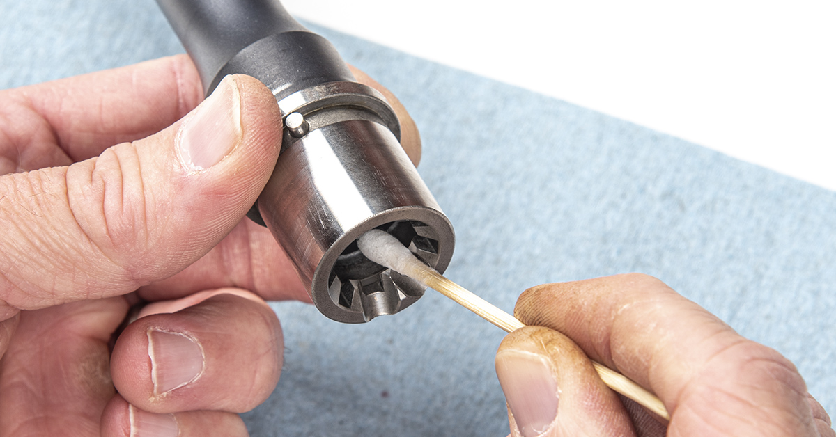
Use denatured alcohol and a fresh swab to thoroughly remove any grease, oils, or debris from the bolt face and lugs. Any contamination can interfere with proper gauging of the chamber length.
Similarly, thoroughly clean the chamber and barrel extension.
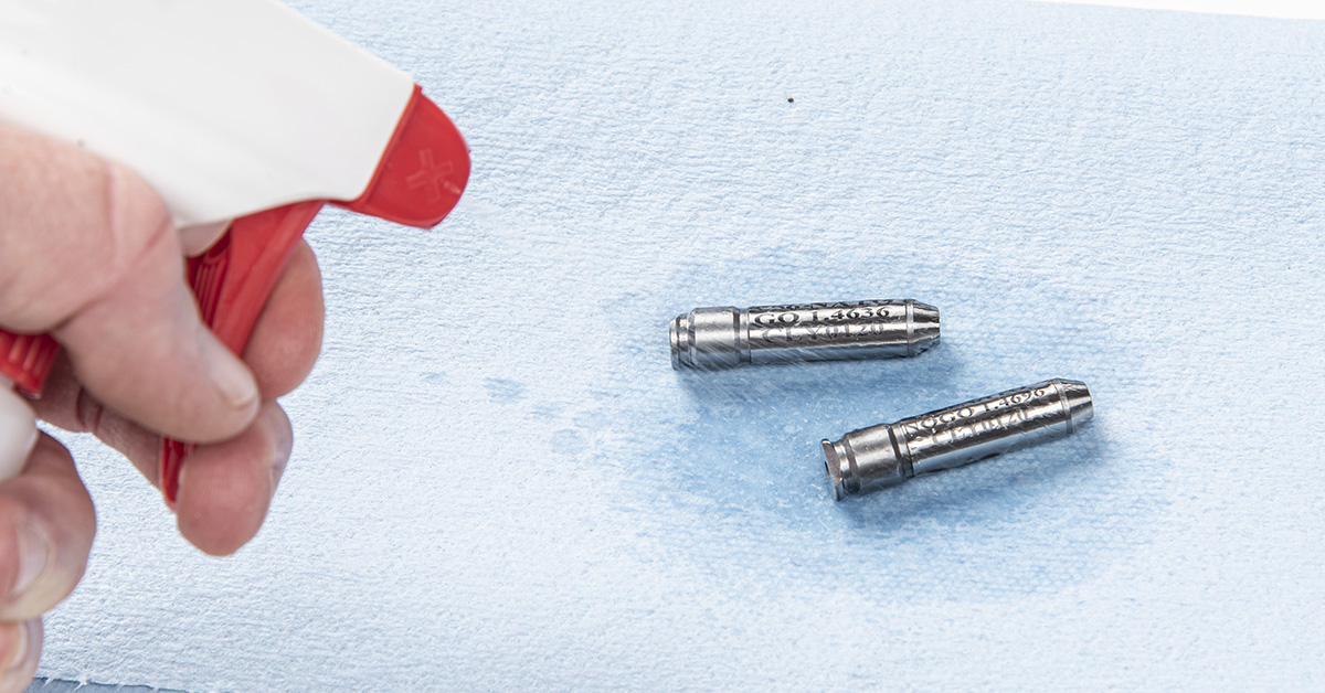
You’ll need a set of GO and NO-GO gauges for the caliber rifle you are building. In this case, we need .223/5.56 gauges. Although we used Clymer gauges here, we recommend gauges from PT&G for Anderson components as they are dimensionally compatible with the PT&G reamers used to machine the barrel chamber. Our Clymer GO gauge was a bit snug in our initial test, but the PT&G GO gauge proved to be spot-on.
As with the chamber and bolt face, clean the GO and NO-GO gauges with denatured alcohol before gauging.
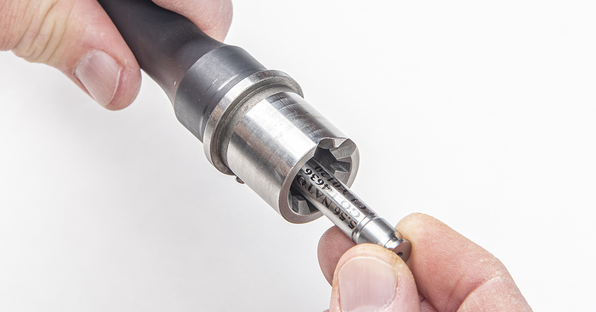
Insert the GO gauge into the chamber. This step is to ensure that the bolt/barrel combination meets the minimum SAAMI chamber length for the .223/5.56. Basically, this is the process of checking for proper (safe) headspace dimension.
With the GO gauge inserted into the chamber, insert the stripped bolt into the chamber. If the bolt/barrel combination is within the safe minimum chamber length, you should be able to turn the bolt freely so that the bolt lugs can rotate in place behind the barrel extension lugs. If the bolt cannot rotate behind the barrel extension lugs with the GO gauge inserted, then the bolt/barrel combination does not meet the minimum SAAMI chamber length, making the combination unsafe to fire. In this case, a new bolt/barrel combination must the acquired.
If the bolt closes on the GO gauge, remove the bolt and GO gauge and insert the NO-GO gauge. Insert the bolt and attempt to rotate it in the barrel extension. The bolt SHOULD NOT be able to rotate behind the barrel extension lugs, indicating that the bolt/barrel combination is within the safe maximum SAAMI chamber length specification. If the bolt does rotate behind the barrel extension lugs with the NO-GO gauge inserted, the chamber length for this combination is too long (excessive headspace) and is unsafe to fire. In this case, a new bolt/barrel combination must the acquired.
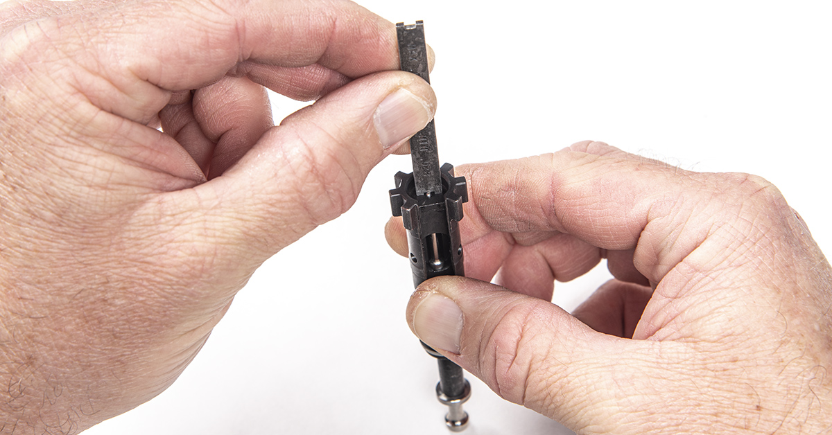
The next step is to ensure that the firing pin protrusion (past the bolt face) is within specification. For this, we use a firing pin protrusion gauge. With the firing pin fully seated in the bolt, run the gauge over the firing pin. The gauge should hit the firing pin at the “minimum” end of the gauge, indicating that the protrusion is greater than the minimum .028 inches. If the protrusion is less than .028 inches, the firing pin may not sufficiently impact the primer.
Flip the gauge over and repeat with the “maximum” end of the gauge. The gauge should slide over the end of the firing pin without impacting it, indicating that the protrusion is not greater than the maximum allowed (.036 inches). If the protrusion is greater than .036 inches, the firing pin may pierce the primer on impact, creating a dangerous condition.
With the critical chamber length (headspace) and firing pin protrusion within specification, we continue with the build.
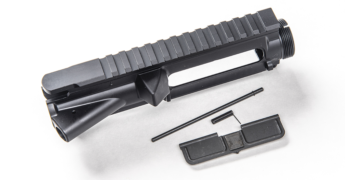
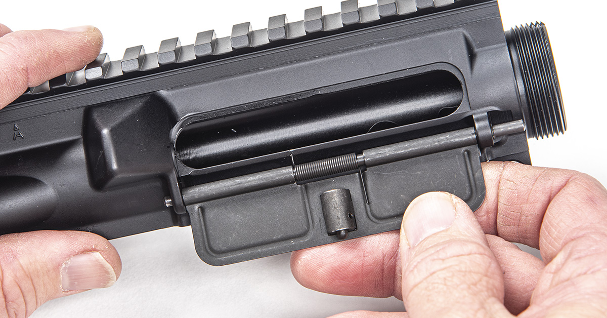
These are the components needed to install the dust cover.
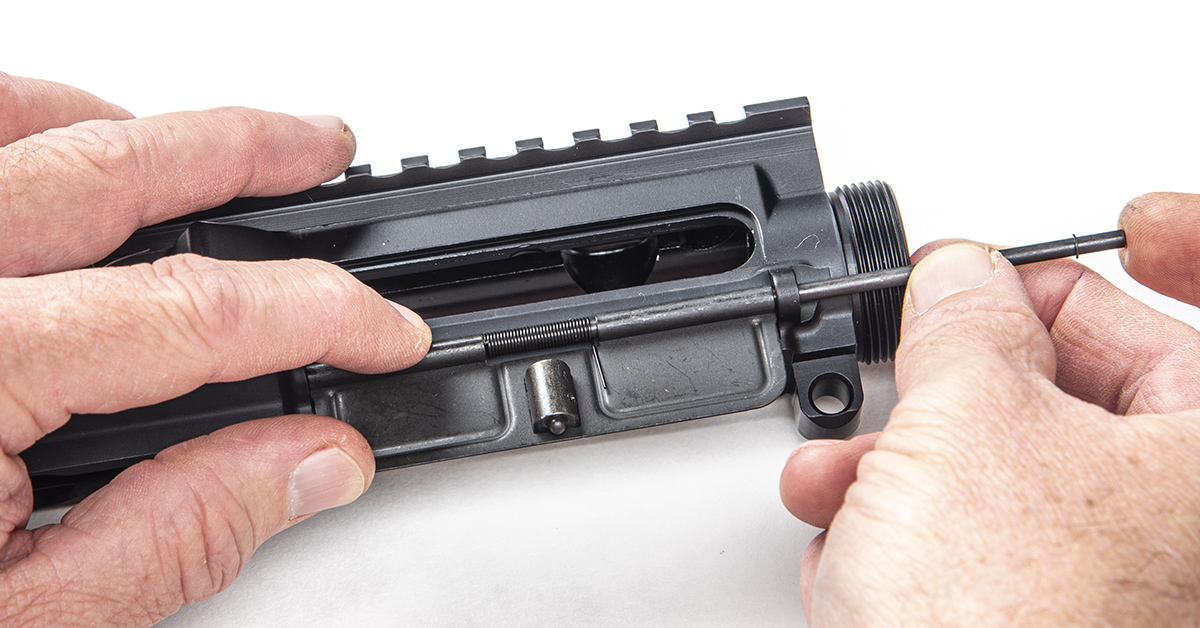
Lightly lubricate the dust cover pin and partially install the cover, pin, and spring onto the receiver as shown, with the pin protruding partway through the open section of the dust cover and spring. The long tail of the spring is to the right (front) of the receiver. This tail end will rest against the inside of the dust cover as shown.
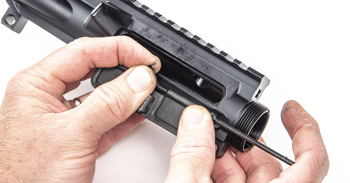
Next (and this is the painful part), grasp the short tail end of the spring and rotate it one complete turn toward you. The objective is to rotate the spring, hold it, and push the pin the rest of the way through the spring, the dust cover, and through the boss to the left of the dust cover. Be patient as you do this as it can be frustrating for the first timer.
This is the dust cover assembly correctly installed. The left side of the spring pushes against the receiver while the right side pushes against the dust cover, creating the necessary tension.
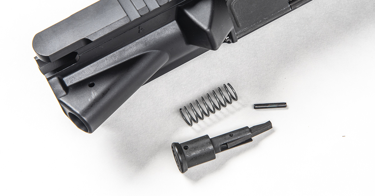
Next, we install the forward assist. This consists of the forward assist, spring, and retaining pin.
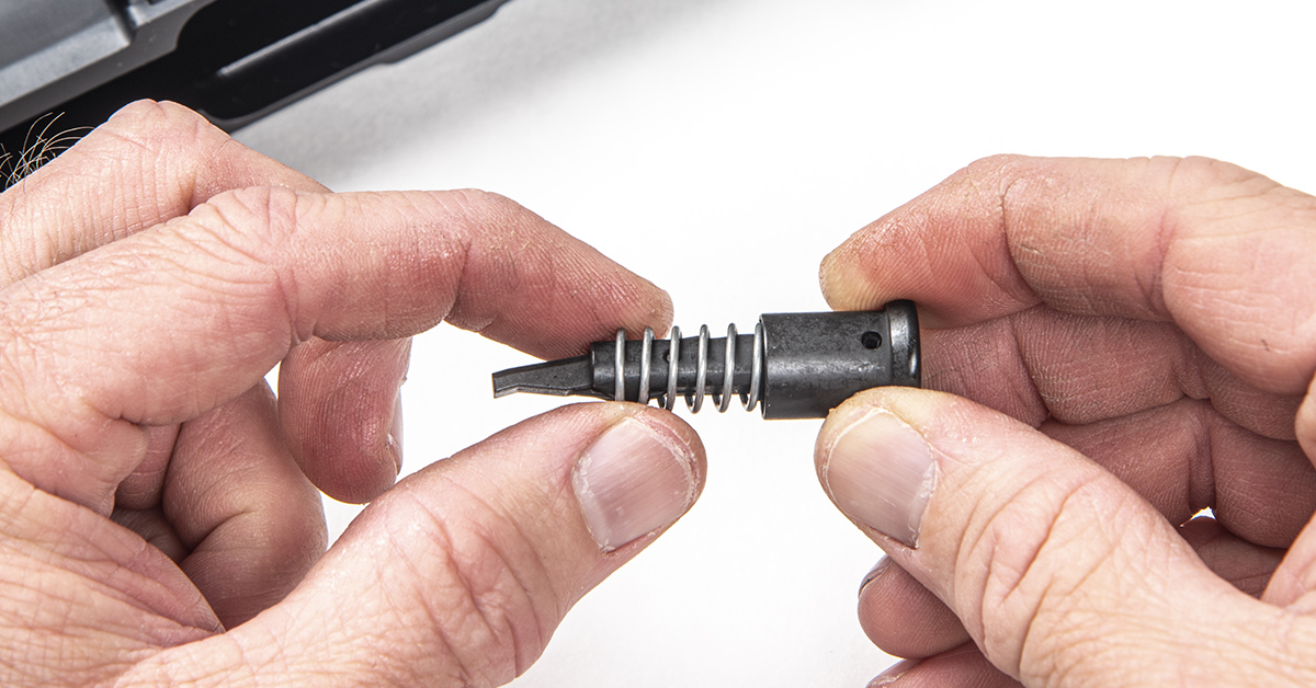
Lightly lubricate the forward assist and spring and install the spring onto the forward assist.
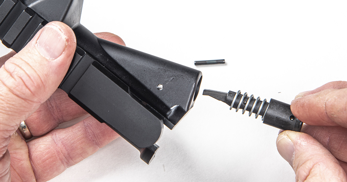
Insert the assembly into the receiver with the curved end of the forward assist pointing toward the receiver as shown.

The Real Avid AR15 Master Bench Block accommodates the upper receiver, allowing the forward assist to be depressed into the receiver and held in place under tension so that the forward assist retaining pin can be installed. Here, we are using a punch to ensure the forward assist is correctly aligned and the roll pin hole is clear to accept the roll pin.
With the forward assist assembly aligned, tap the roll pin in place with a roll pin punch.
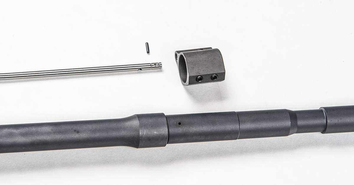
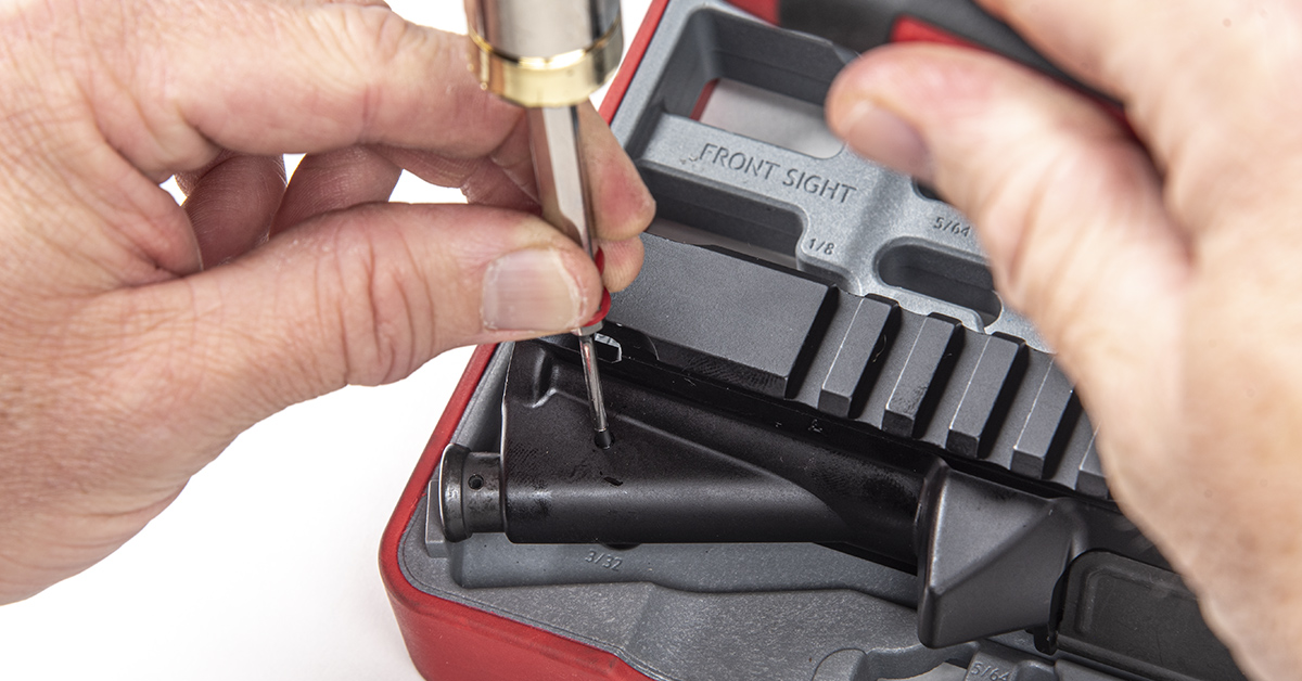
Next up is the gas tube and gas block assembly. A small roll pin secures the tube to the gas block.
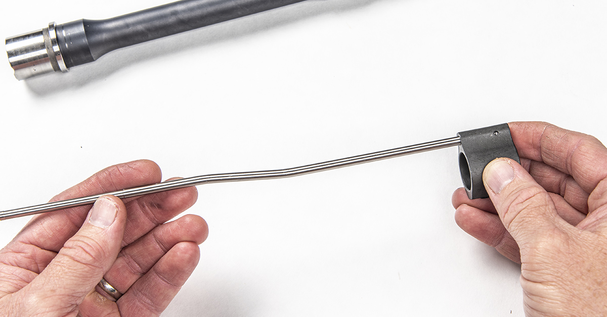
Insert the forward end of the gas tube (the closed end with the gas port and roll pin hole) into the back of the gas block as shown and rotate the gas tube so that the bend is oriented “up.”

Start the roll pin into the gas block just enough to stay in position. Insert a punch through the opposite hole to make sure the gas tube pin hole is still aligned with the gas block pin holes.
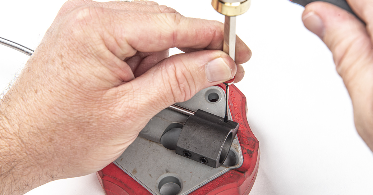
Now here’s another aggravating step that often requires some deep breathing and a lot of patience when working with a low-profile gas block. With the gas tube correctly aligned in the gas block, you’ll need to secure the two with the small gas tube roll pin. The challenge is that the gas block wants to roll when driving in the pin. Sometimes you get it right the first time; sometimes it takes a few attempts. Good luck!
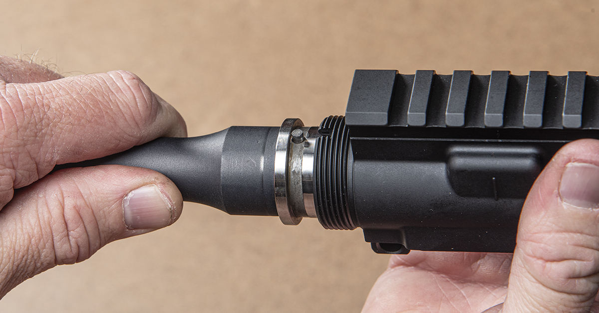
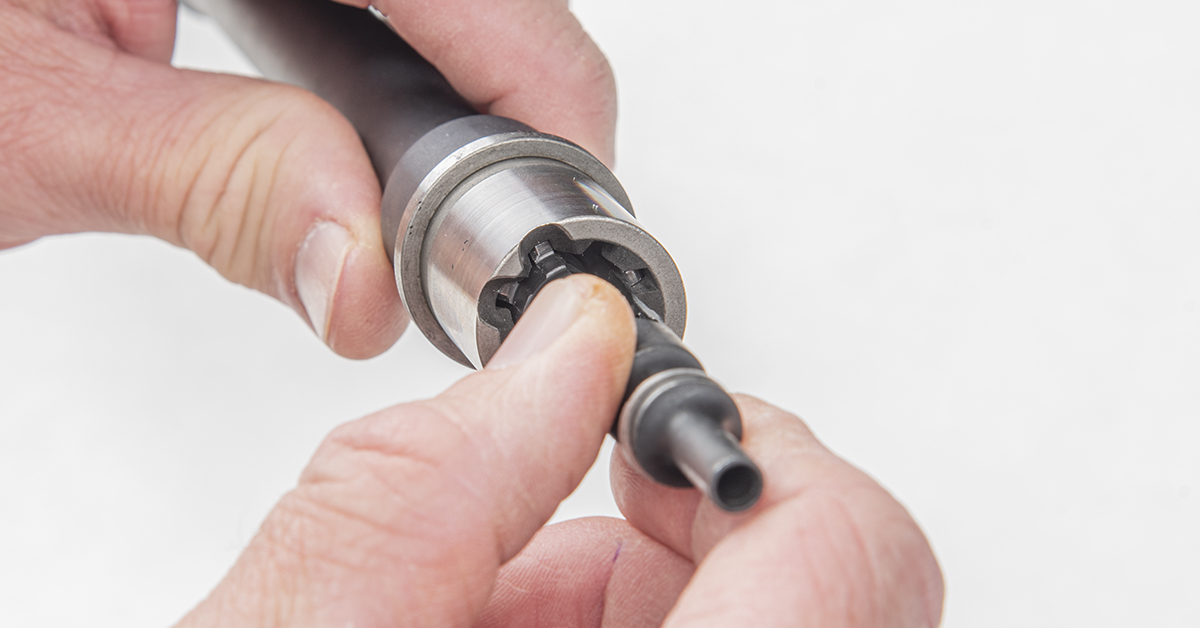
The remaining steps are accomplished with the upper receiver assembly secured in a bench vice. For this, we are using Real Avid’s Lug-Lok Upper Vise Block. You can also use a commercially available AR-15 upper receiver vise block. With the upper receiver secured in a vise, lightly lubricate the barrel extension, and insert the barrel into the receiver. Be sure the indexing stud mates with the notch in the receiver threads.
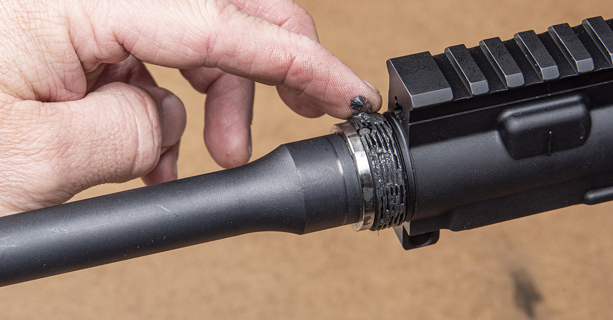
Lubricate the receiver threads with molybdenum grease.
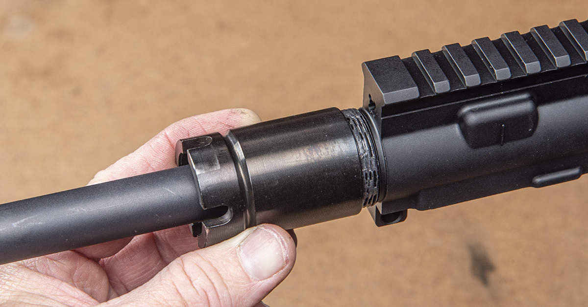
Thread the barrel nut onto the receiver hand tight.
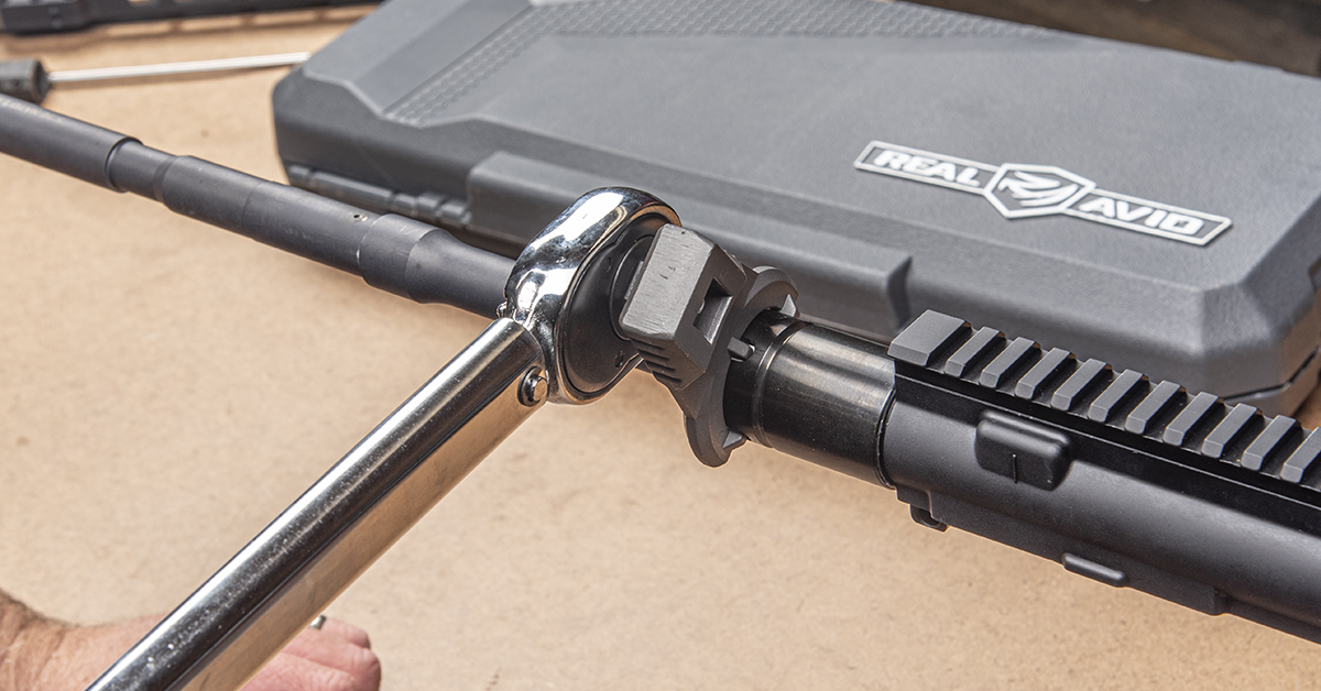
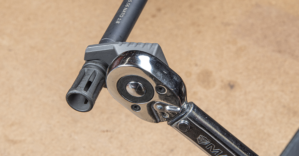
Use a ft-lb torque wrench and the appropriate barrel nut wrench to secure the nut. This is a three-step process. Set the torque wrench to 30 ft-lbs and tighten the nut. Loosen the nut with a standard wrench (never loosen with a torque wrench) and tighten the nut again to 30 ft-lbs. Loosen the nut again and tighten the nut to a final 30 to 80 ft-lbs. We typically set the torque at 50 to 60 ft-lbs.
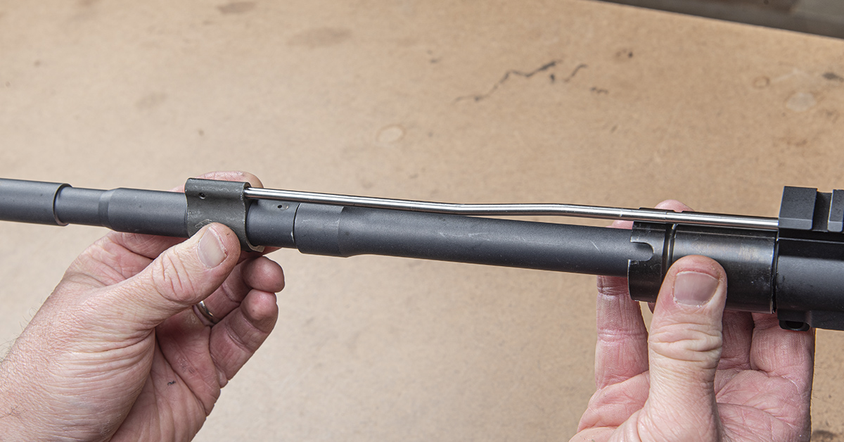
Slide the gas block and tube assembly onto the barrel, guiding the gas tube into its hole in the receiver. Be sure to push it all the way until the gas block stops against the machined “shoulder” just behind the gas port. The gas block must be in a vertical orientation with the barrel to ensure the barrel and block gas ports are aligned.
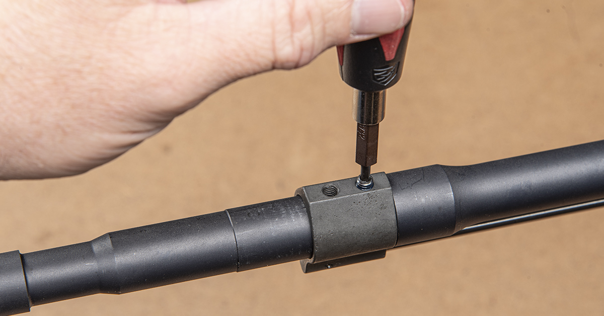
Most low-profile gas blocks use set screws to secure them to the barrel. Clean the screw threads with denatured alcohol, apply a small amount of high-strength thread locker to the threads, and tighten.

Moving to the muzzle, apply molybdenum grease to the threads and install the supplied crush washer in the orientation shown (cupped end facing the muzzle, tapered end facing the barrel shoulder).
Tighten the flash hider or muzzle device to 15-20 ft-lbs. You want to make sure that the flat, unslotted portion of the muzzle is oriented down at the final torque setting.
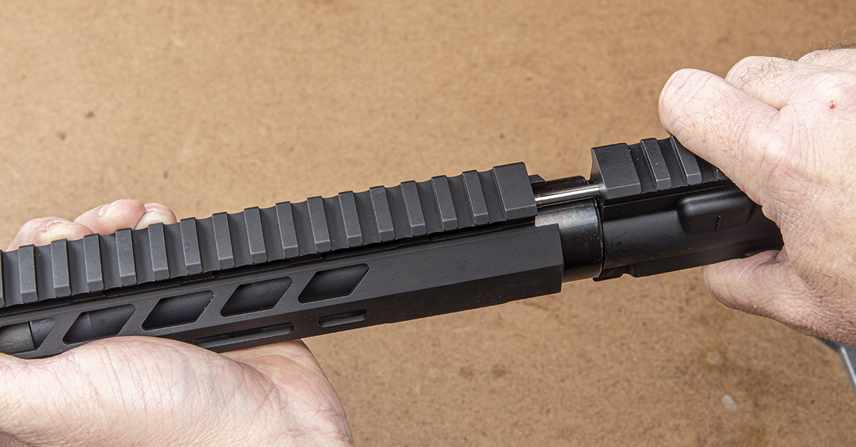
Install the handguard onto the barrel nut, making sure to align the Picatinny rail top even with the receiver top rail.
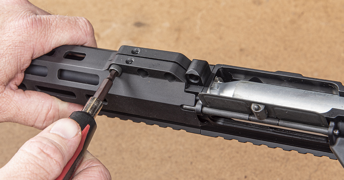
Clean the provided mounting screws (two on the bottom and three on the side) with denatured alcohol, apply medium-strength thread locker, and tighten.

Assemble the upper and lower receiver and perform a function check to ensure the rifle is operational. This includes checking that the safety and fire positions work, and that the trigger reset works. Check also that the magazine correctly seats in the receiver and that the magazine drops freely when depressing the magazine release button.
Before test-firing the gun, it is recommended to clean the bore to ensure it is clean and all manufacturing oils or debris have been removed.
During initial testing, be sure to wear gloves and safety glasses, and that no one is nearby on the firing line. Insert one round into the magazine, chamber the round, and fire. If successful, insert two rounds in the magazine and fire the two rounds. If the gun successfully fired both rounds, add five rounds to the magazine and repeat the firing sequence. Also, examine these initial empty cases, looking for surface anomalies and primer impact. The primer should have a modest firing pin indent—not too light and not too deep.
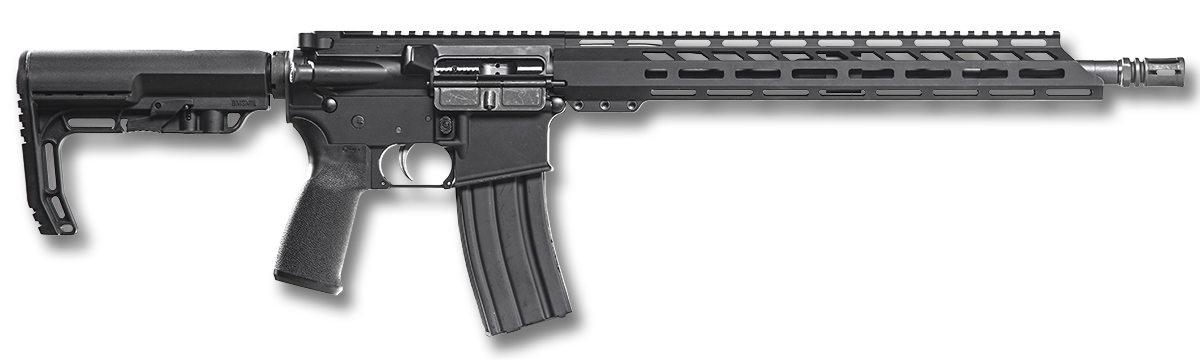
Congratulations…you’ve built an AR from a box of parts!
Sig Sauer Tango-MSR LPVO 1-6x24mm
If you haven’t noticed, LVPOs (low-power variable optics) are gaining a lot of steam in the AR world, and for good reason. Their relatively low magnification range of 1X-4X or 1X-6X provide a single optic solution that expands an AR-15’s functionality. The low power provides the rifle fast sight picture acquisition for close-quarter engagement, such as in a personal defense situation, while the higher magnification settings allow the shooter to effectively engage targets way out there.
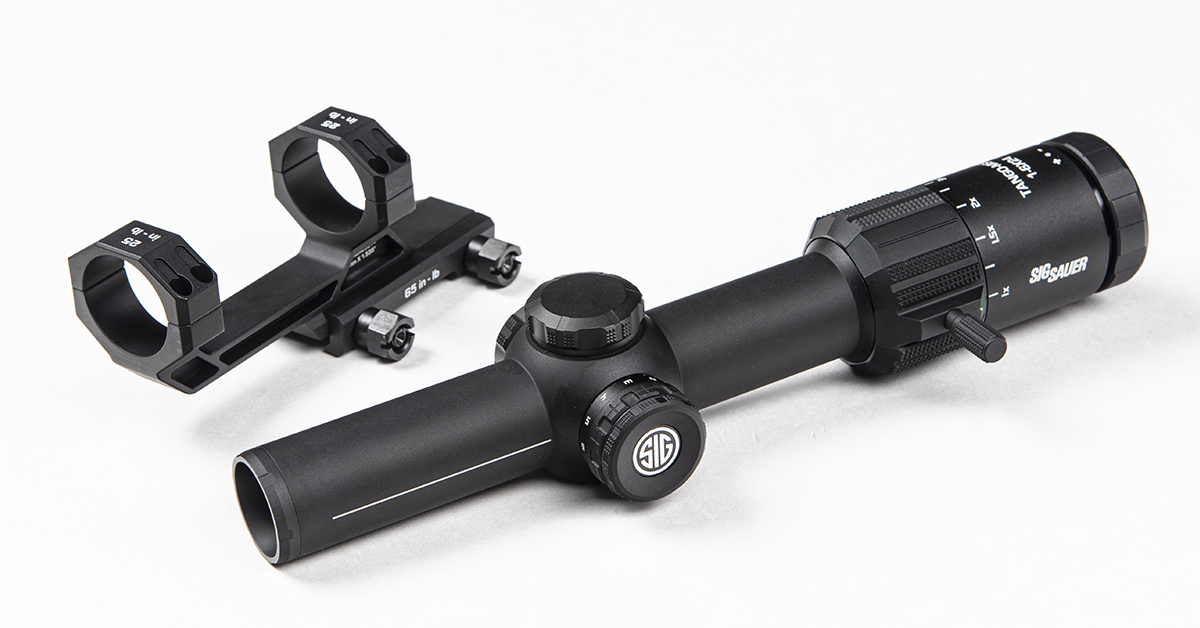
For our Anderson Mfg. rifle build, we wanted to give the new Tango-MSR LVPO 1-6x24mm from Sig Sauer a try. This illuminated reticle optic boasts a 30mm tube, BDC reticle, removable throw lever, and comes with the ALPHA-MSR one-piece cantilever mount.
Stay tuned for a stand-alone review of this promising optic…