In the second of our three-part series, we break into the 1911 frame assembly for some cleaning and spring replacement
by Lou Patrick
When we left part one of our 1911 Deep Dive series, we had completed all the work necessary on the slide assembly, with the slide clean, lubricated, and ready for installation onto the frame. In this installment, we take the same approach with the frame assembly, showing you how to disassemble all the critical components, clean, inspect, and reassemble it all.
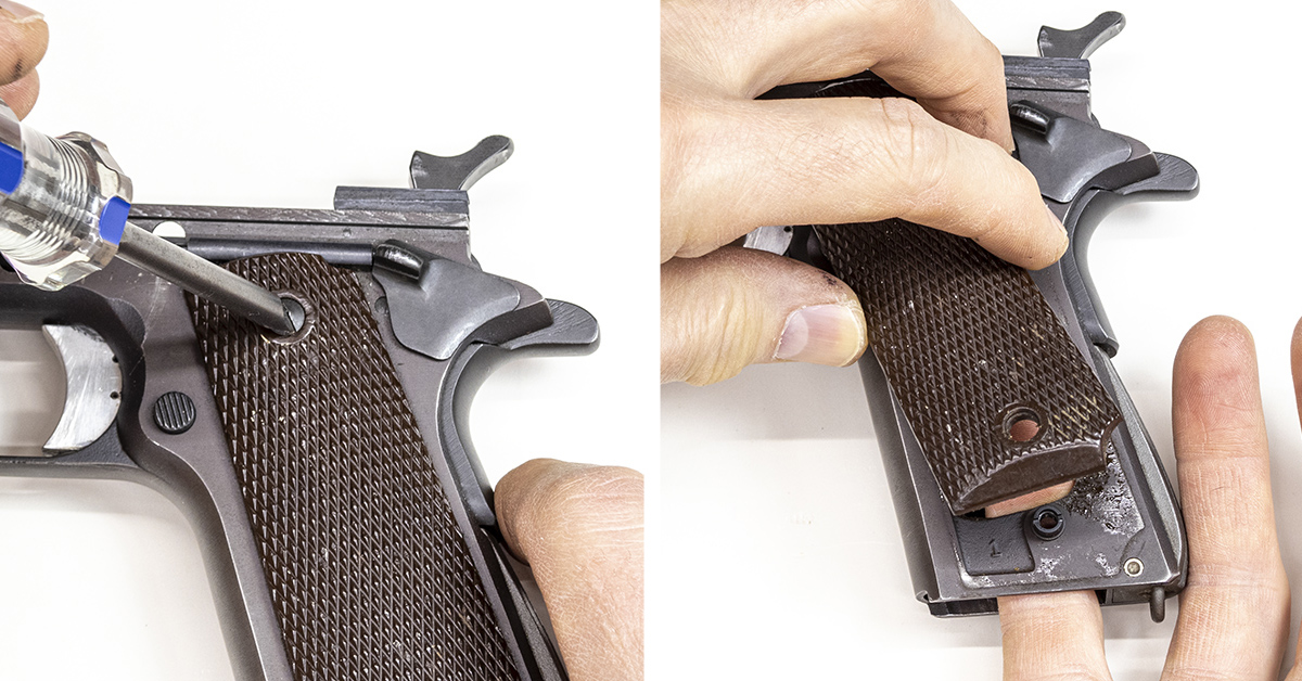
Remove the grip screws and the grip panels. If the panels do not easily lift off the frame, DO NOT attempt to pry them off. Insert your finger into the mag well (right) and push up on the grip panel.
With a small screwdriver, turn the magazine release screw 90 degrees counterclockwise and remove the magazine release. There is a small tab on the head of this screw that needs to align with a small groove within the magazine release. You will need to push inward on the magazine release in order to gain alignment. Once alignment is achieved, the screw will turn easily. Remember, it will only turn 90 degrees. If you find the screw difficult to turn, rather than using more force to turn the screw, work to gain proper alignment.
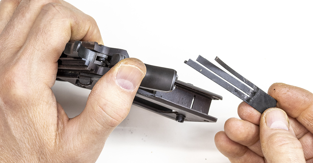
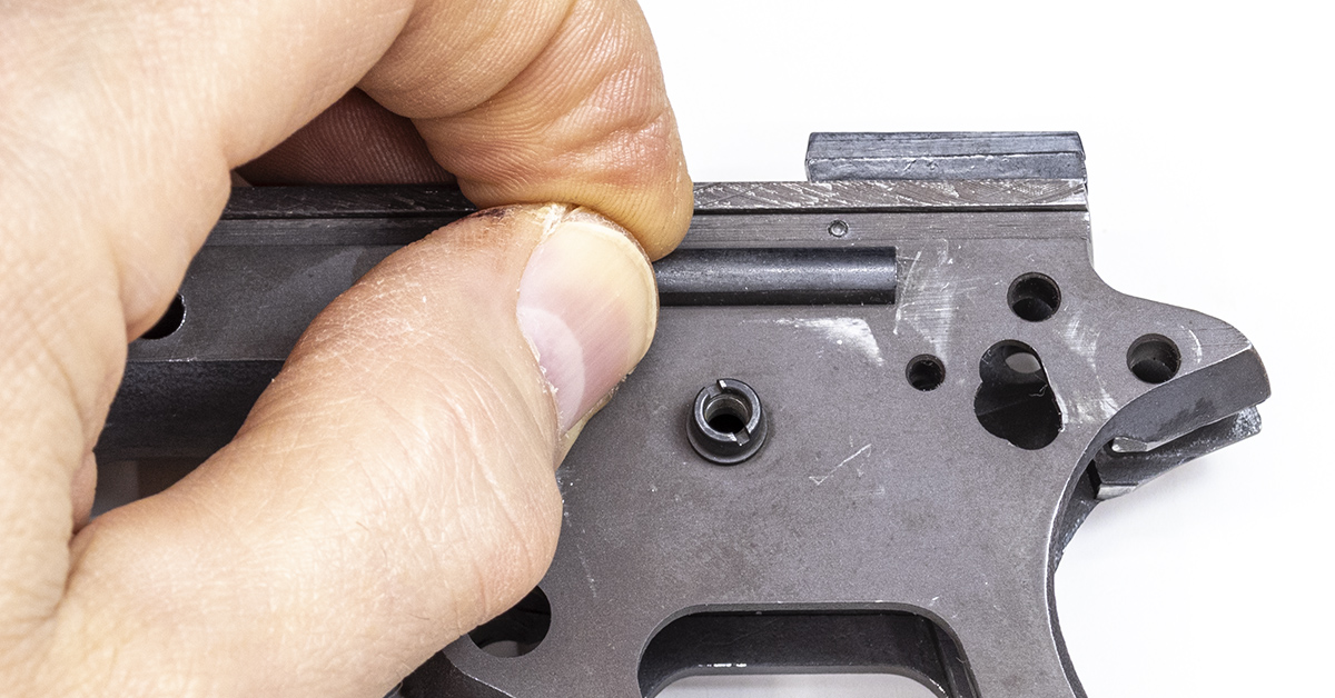
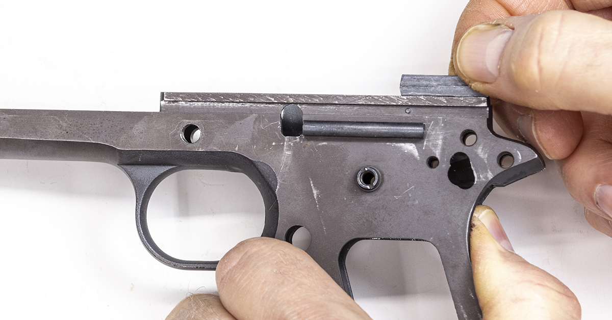
The hammer spring is captured within the main spring housing via the pin seen here. Before removing the main spring housing, check to ensure that the housing on your 1911 has this pin in place. If this pin is not present, once the housing is removed from the frame, there is nothing to contain the force of the 23-lb. hammer spring.
Place the frame on a bench block. Using a hammer and punch, remove the mainspring housing pin and drive the pin from the left to the right. Once the pin is removed, the housing will slide downward and out of the frame.
The sear spring easily lifts up and out of the frame. Remove the sear spring.
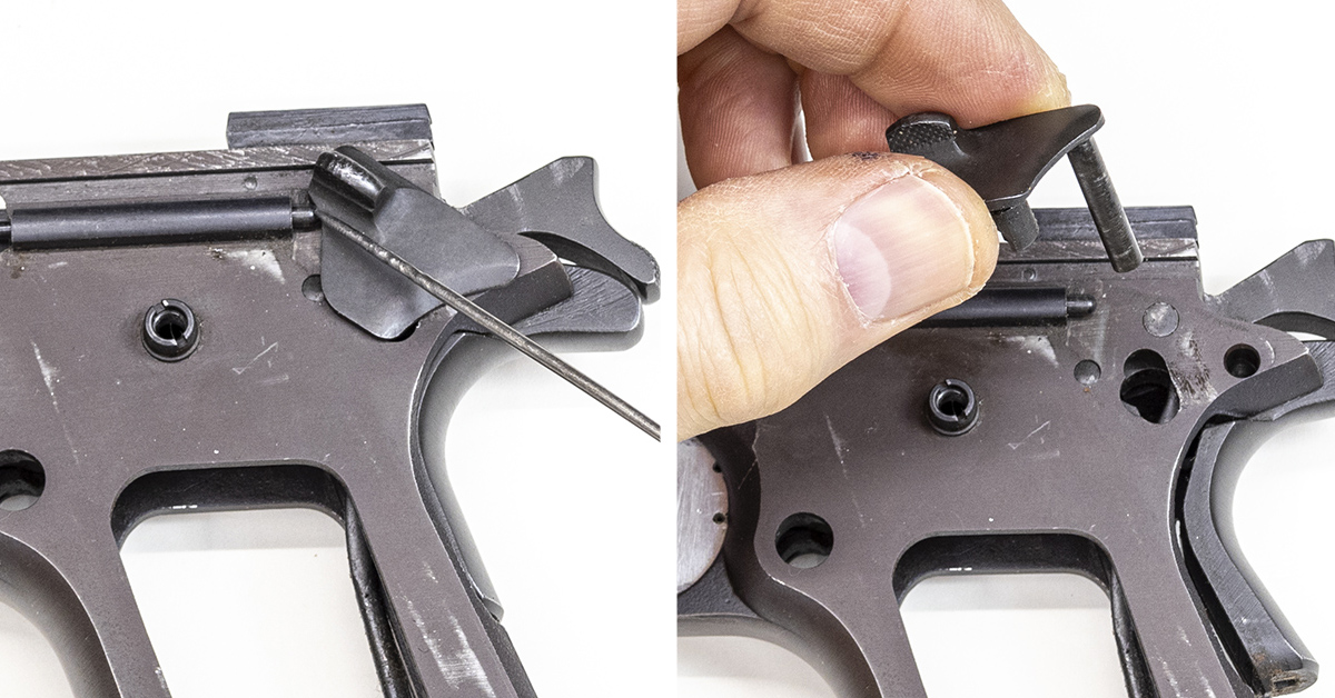
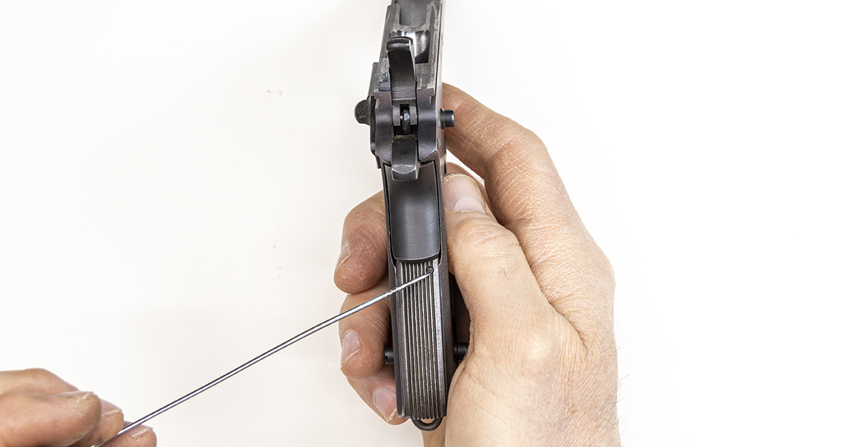
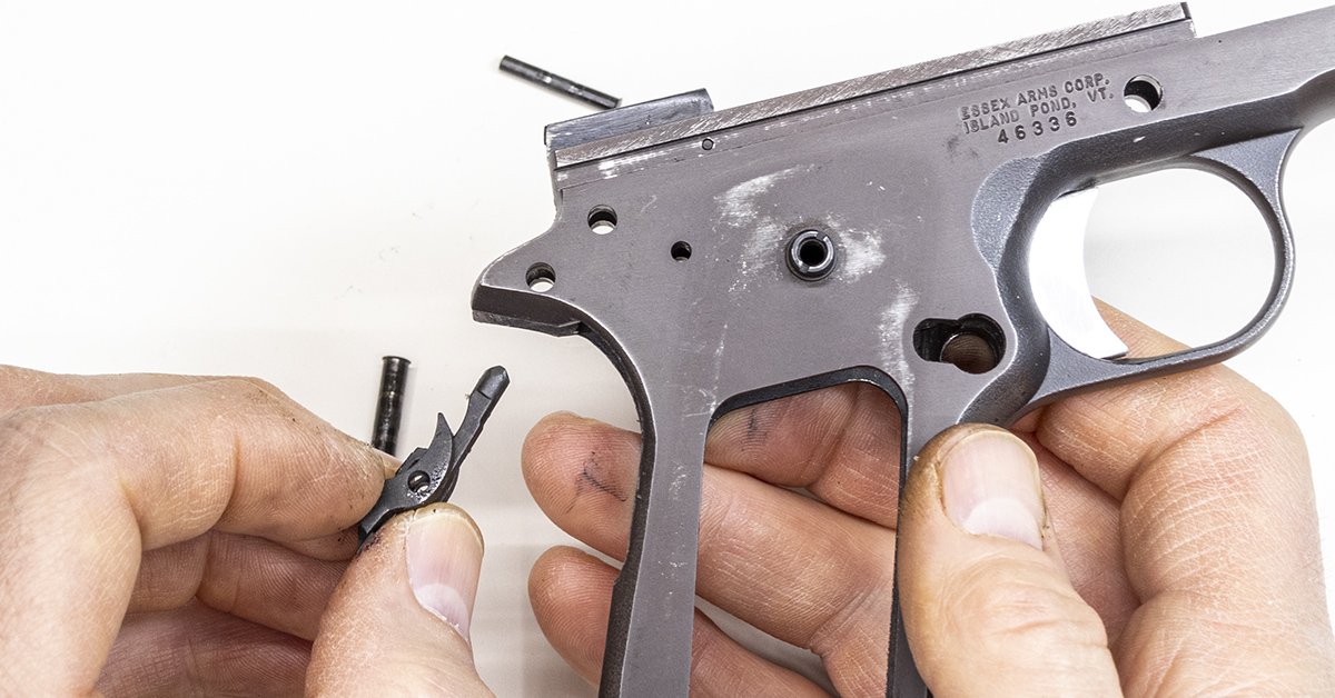
There is a spring-loaded detent that engages the thumb safety, holding it in the desired position. With the hammer back, use a small jeweler’s screwdriver to push the detent into the plunger tube while simultaneously lifting the safety up and out of the frame. Carefully control the spring tension of the safety detent while removing the thumb safety. It is the safety that holds the detent in place. Once removed, the detent may fly off to parts unknown unless you maintain control of it.
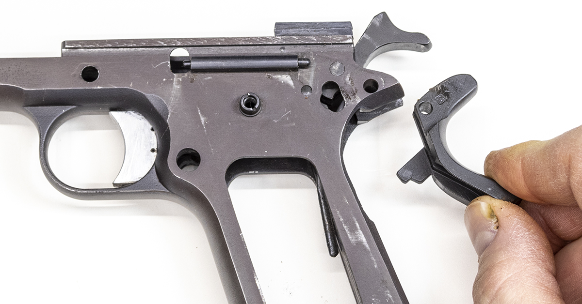
The thumb safety also holds the grip safety in place. Remove the grip safety.
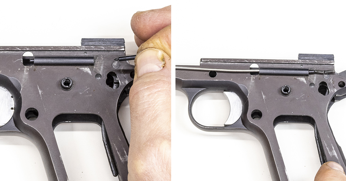
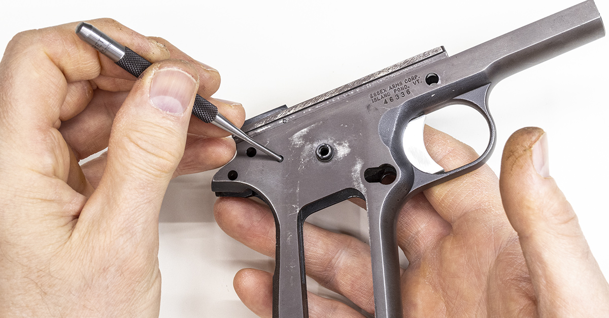
Remove the safety detent (left). Starting at the left end of the plunger tube (right), push the slide stop detent and spring through the tube and out the right side of the tube.
Use a punch to remove the hammer pin from right to left, as shown. This pin should come out easily with hand pressure.
Remove the hammer. The hammer strut is attached to the hammer with a small retaining pin. Notice how the hammer strut curves rearward towards the hammer spur.
Use a punch to remove the sear pin from right to left, as shown. This pin should also come out easily with hand pressure.
Remove the sear and disconnector. These two components will separate easily once the sear pin is removed and may separate during pin removal.
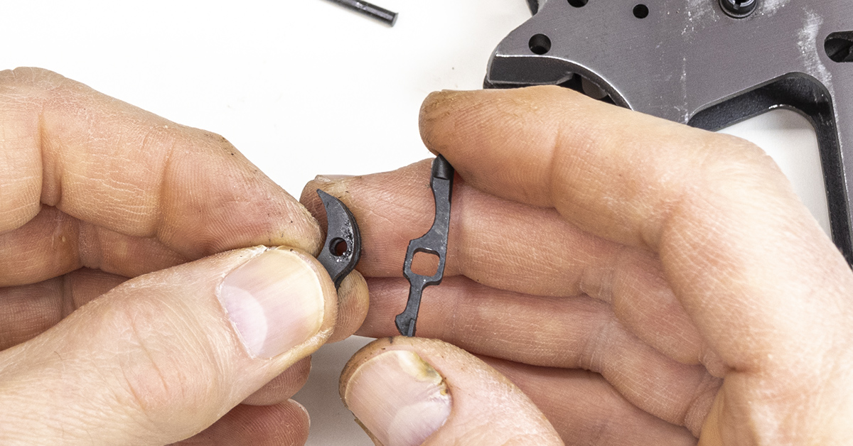
The sear is held in my left hand and the disconnector is in my right. During reassembly, hold the parts as pictured. The disconnector will slide into the slot in the center of the sear. Align the holes of each component, as the sear pin secures both parts in place.
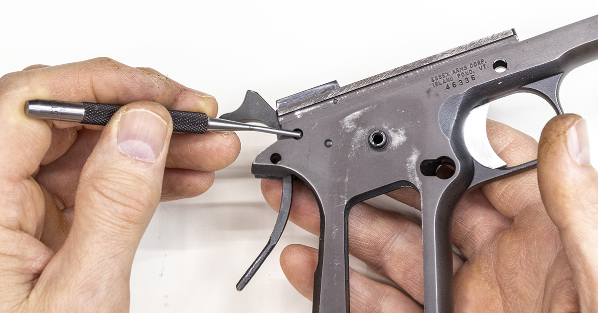
Slide the trigger rearward and out of the frame.
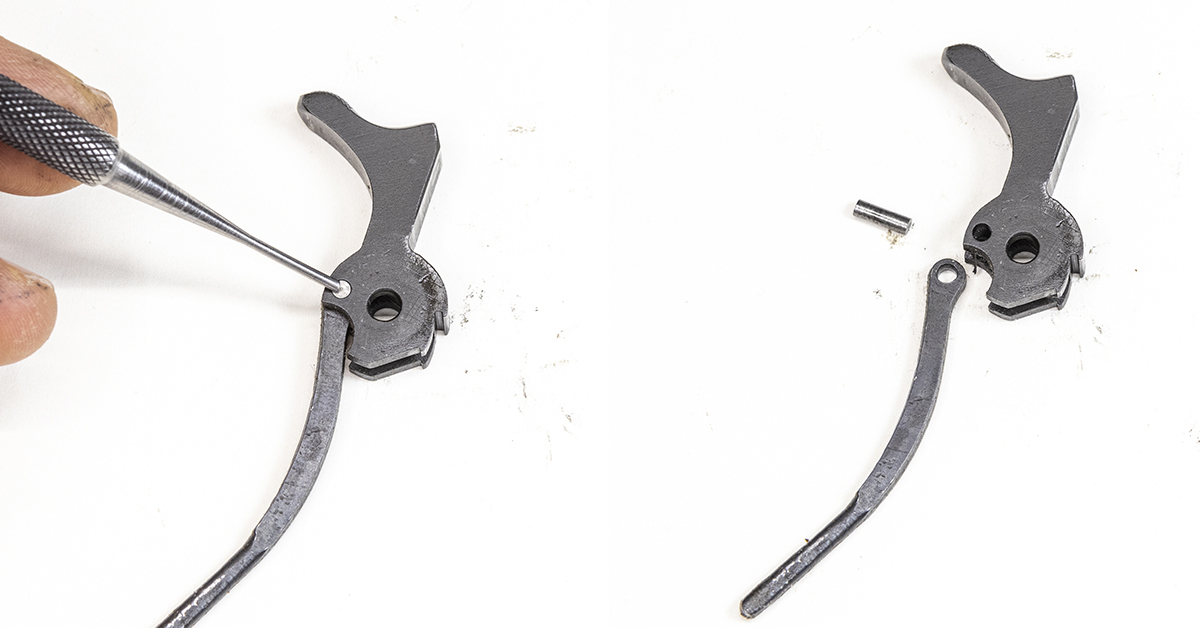
Use a hammer and punch to remove the hammer strut pin.
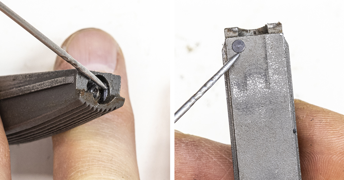
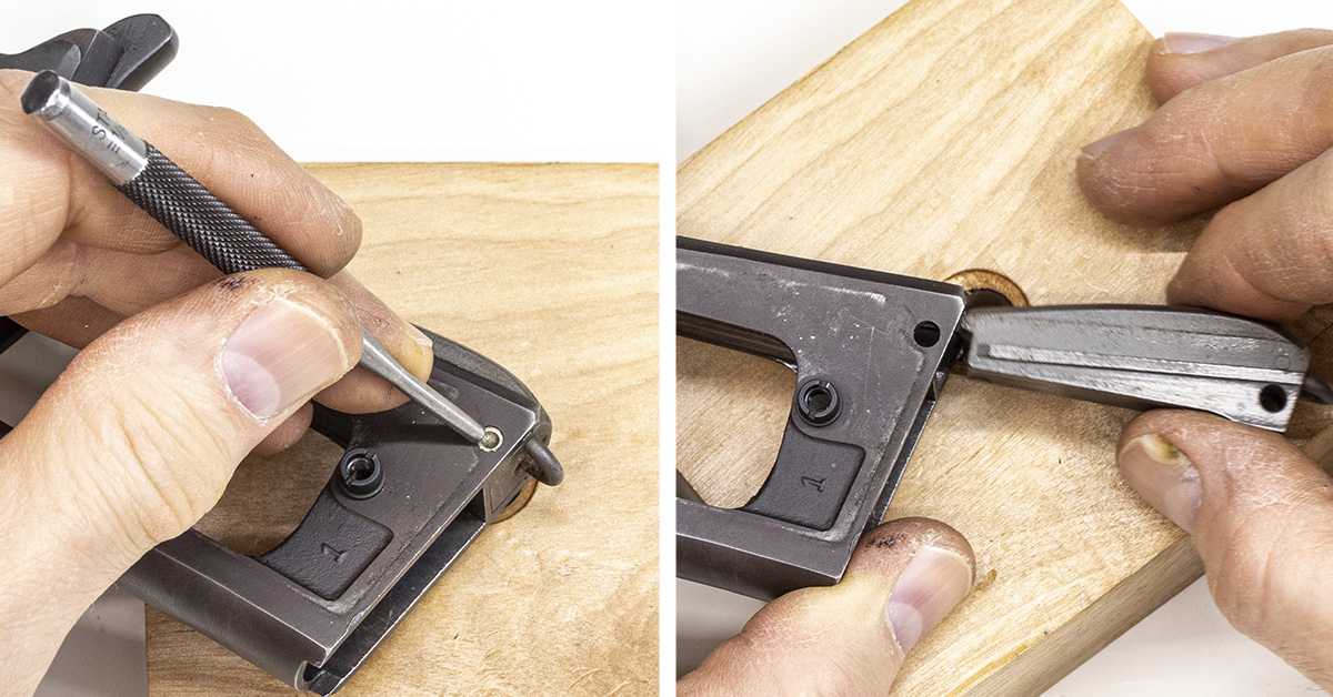
The hammer spring is held in place and under partial compression by the retaining pin (left). One end of this pin is flared (right). Because of this flared end, the pin can only be removed in one direction.
Using a bench block, hammer, and a punch, remove the retaining pin (left), driving the punch completely through the housing. The spring tension is now being held by the punch. Maintain a firm grip on the housing (right), with the end of the housing in contact with the bench block. Carefully remove the punch as you maintain control of the spring tension.
Carefully release the spring tension and remove the hammer spring assembly from the mainspring housing.
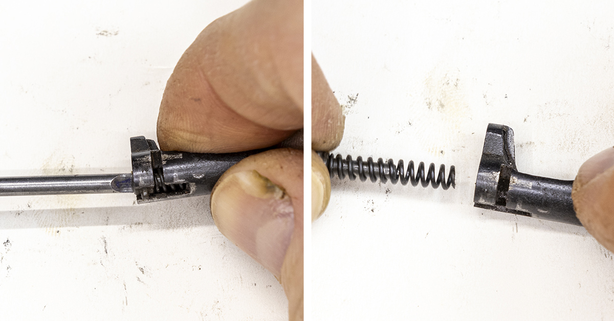
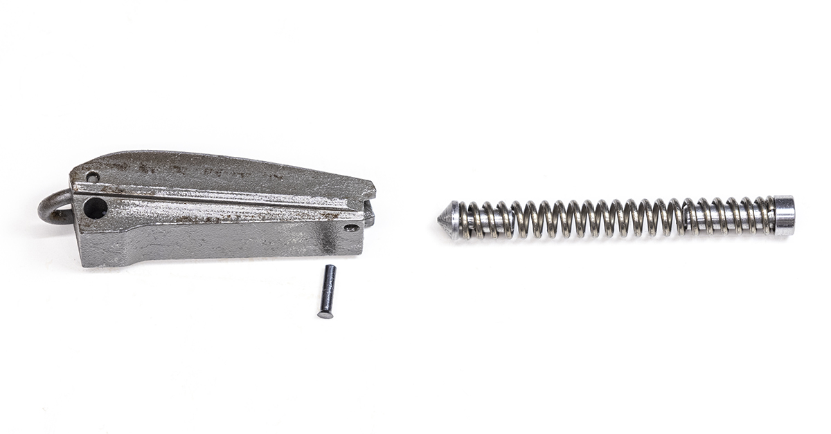
Remove the cap and the housing pin retainer from the hammer spring. The housing pin retainer has a conical shape on one end and installs at the bottom of the hammer spring. Look closely at the mainspring housing pin that you removed earlier and you will see a groove in the center of the pin. The conical shape of the housing pin retainer will engage this groove, holding the pin in place. The hammer spring cap has a smooth beveled surface that will engage the end of the hammer strut.
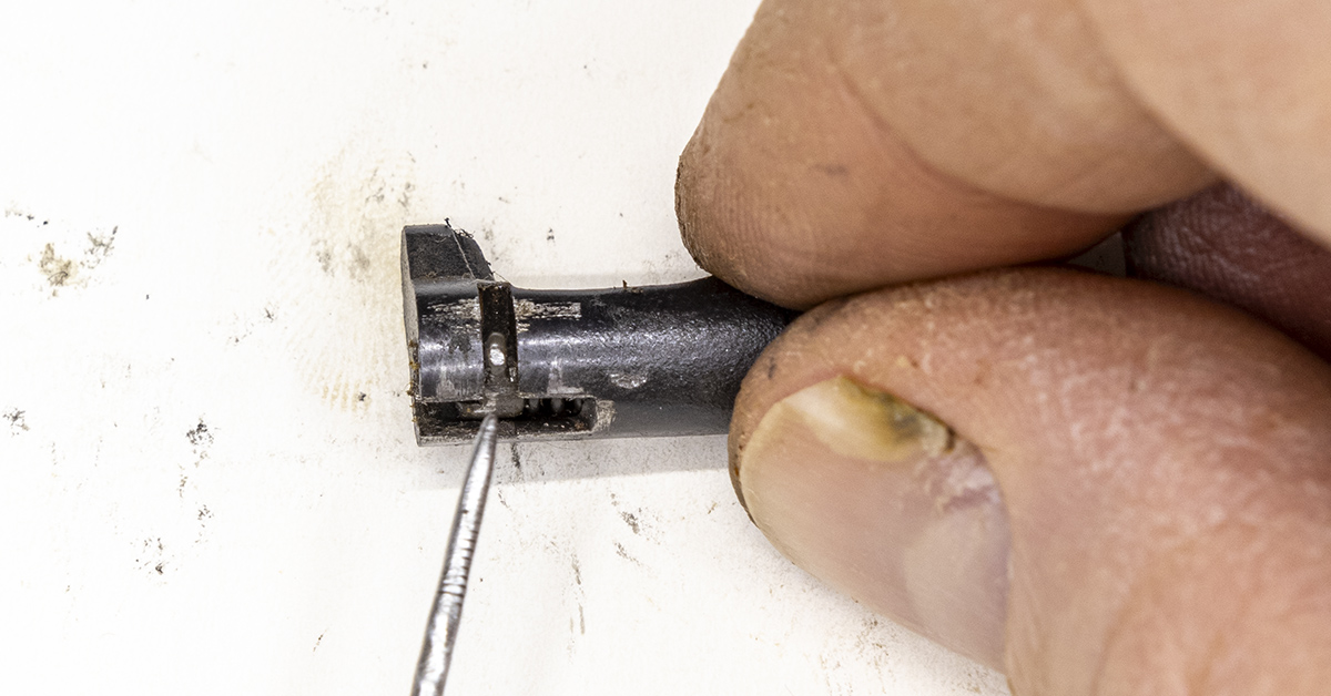
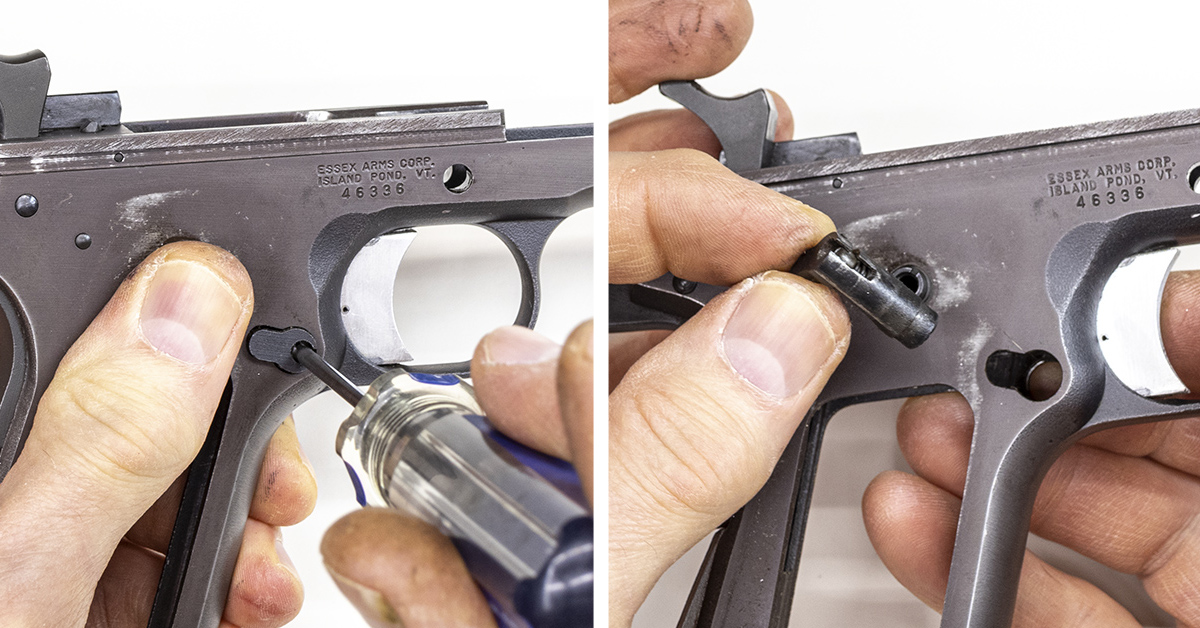
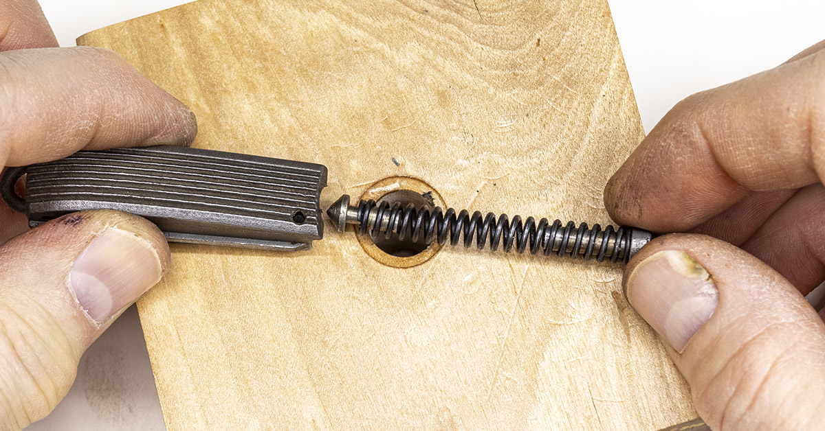
The head of the screw on the magazine release has a small tab on it that engages this slot, allowing for removal of the assembly from the frame. During reassembly, the screw is turned, and this tab will then engage the frame, holding the assembly in place.
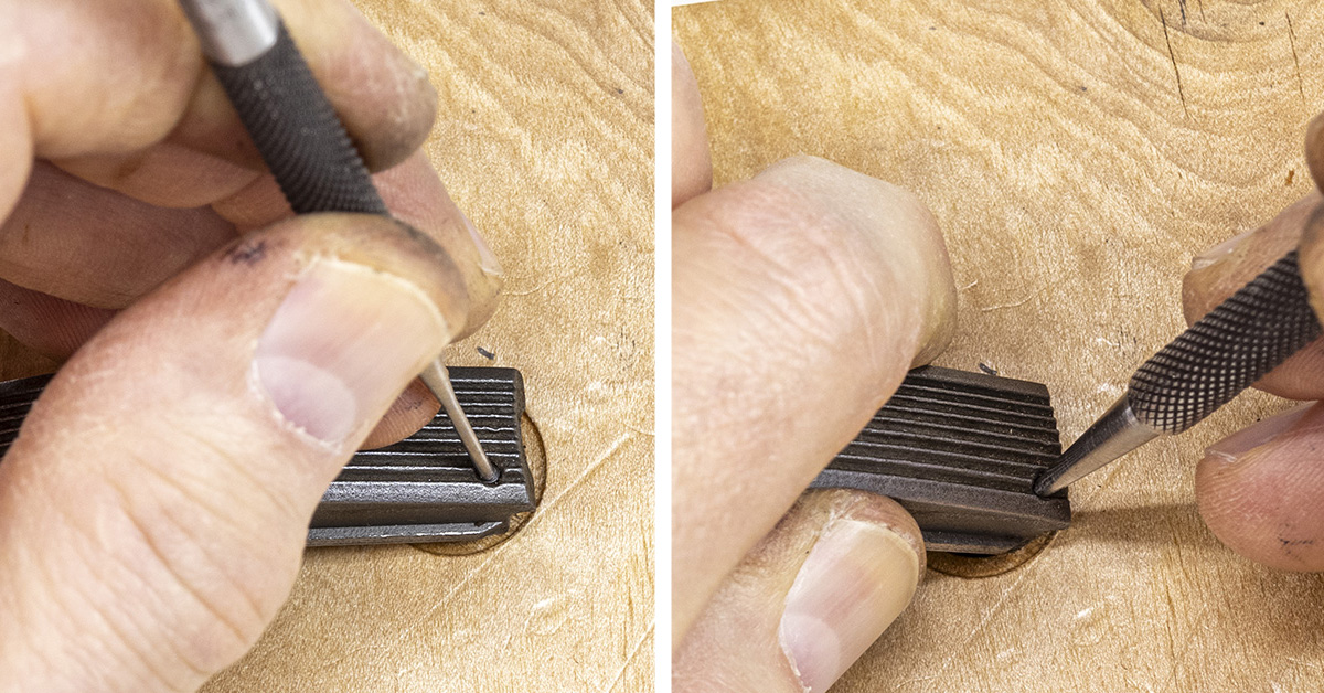
To further disassemble the magazine release, maintain control of the spring tension and use a screwdriver to rotate the screw clockwise so that the tab will move into the slot located on the magazine release (left). Remove the screw and the magazine catch spring (right).
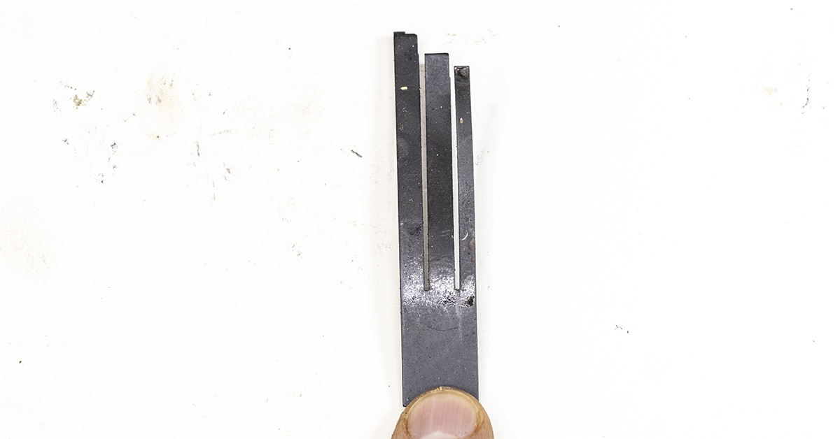
The sear spring contains three separate tines that provide four separate functions. The sear spring is pictured as it would be if installed in the pistol. The tine on the far left provides pressure on the bottom left corner of the sear. The center tine provides pressure for the operation of the disconnector and acts as a trigger return spring. The tine on the right provides spring pressure for the grip safety. When working on your 1911, be careful when handling the sear spring. An unintentional bending of the tines will affect the pressure provided by that tine and can have a negative impact on the operation of your pistol.
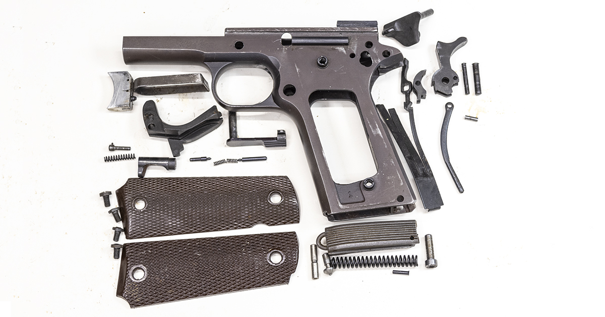
As with the slide components, thoroughly clean and degrease the frame and all the small parts. Inspect each part as you clean, looking for any abnormalities such as burrs and signs of excessive wear.

The trigger in this 1911 is an aftermarket trigger that contains a small screw that is used to adjust for overtravel. If your trigger has this adjustment screw, be careful, as you do not want to turn the screw and lose adjustment as you work.
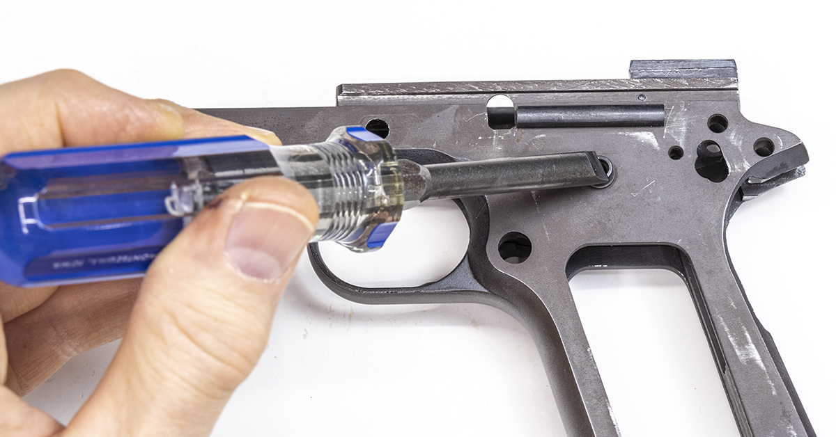
Use a screwdriver to ensure that the grip bushings are tight. The bushings were originally staked in place and are not easily removed. You are not trying to remove the bushings; you simply want to ensure that they are tight and will remain tight. It is not uncommon for the grip bushings to come loose after years of use. If the bushings are loose, use denatured alcohol and degrease the threaded hole in the frame and the threads of the bushing. Apply red Loctite 262 to the threads of the bushing and tighten the bushing in place.
Ensure that the plunger tube is tight. The tube should be rigidly attached to the frame with no perceptible movement. Plunger tubes were originally staked to the frame. If the tube is loose, it is best to seek assistance from a gunsmith, as you will need a special tool to stake a new plunger tube in place.
The ejector is also staked to the frame. Check to ensure that it is tight to the frame with no perceptible movement. If the ejector is loose, seek assistance from a gunsmith to have a new ejector staked in place.
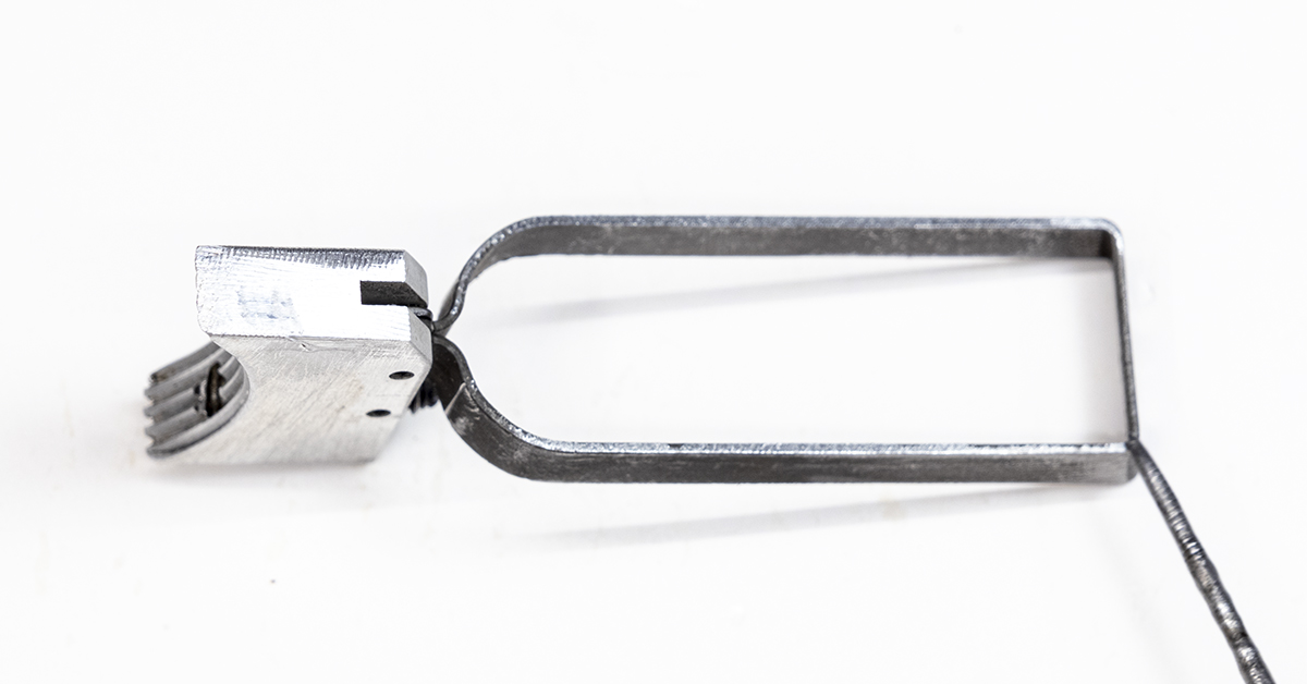
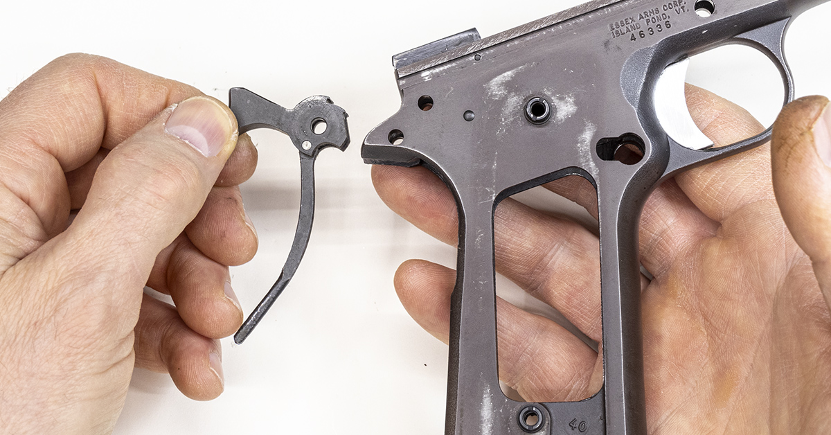
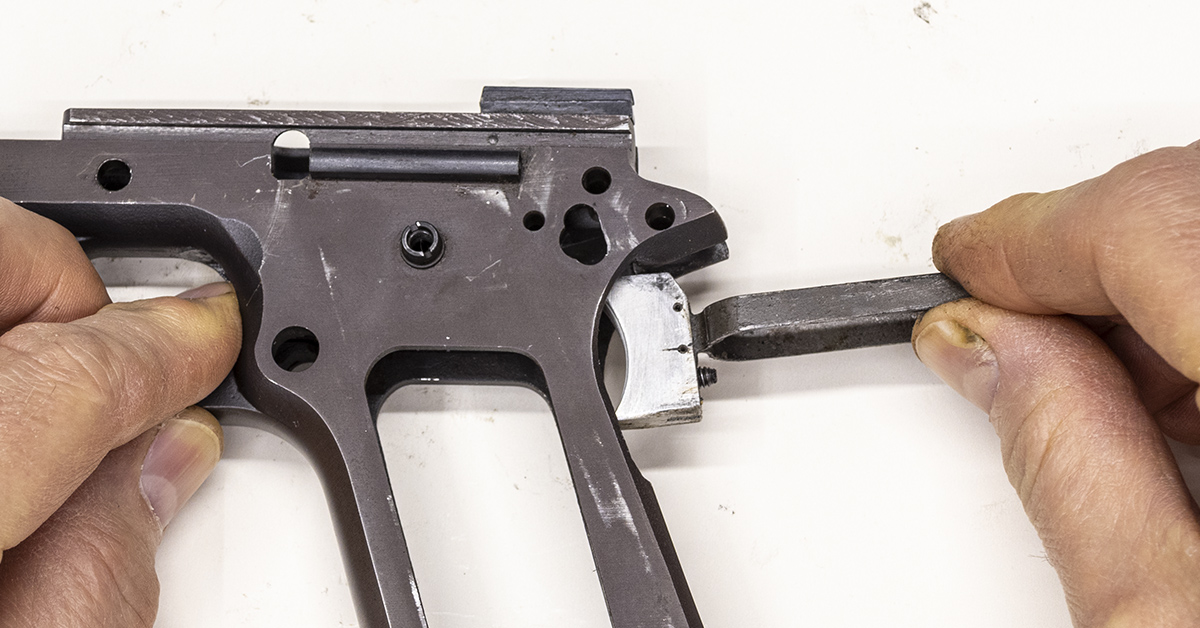
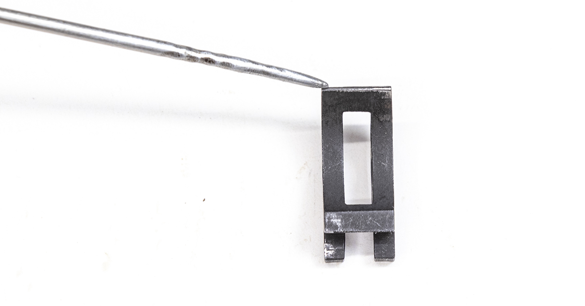
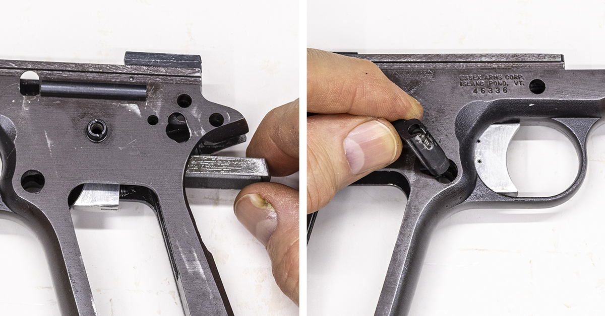
Any abnormalities in the trigger bow can have a negative impact on the operation of the trigger. Check to ensure the trigger bow has the proper shape, as pictured. If the bow is slightly bent out of shape, trigger bow shaping dies are available that can be used to correct the problem.
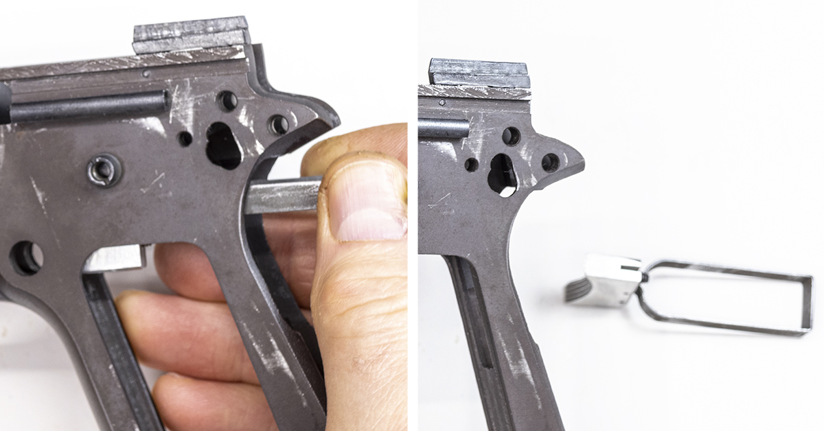
The trigger should slide easily in and out of the frame (left). With the trigger fully inserted into the frame, as you invert the frame (right), the trigger should fall out of the frame under its own weight.
Check the engagement surface of the sear. This should be clean and free of imperfections.
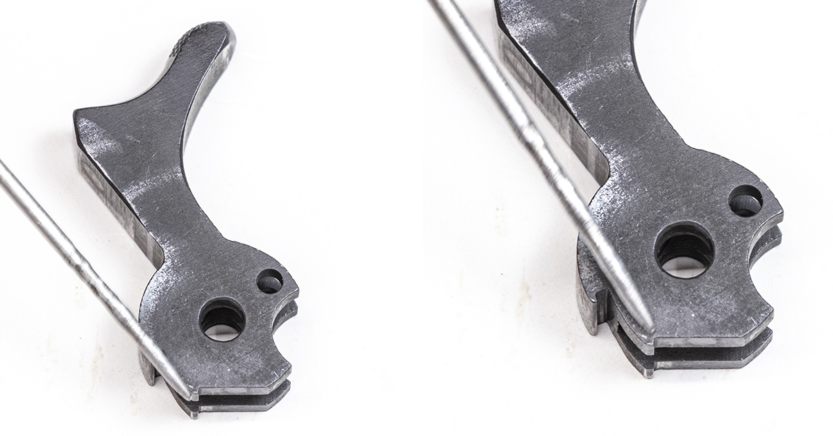
The hammer hooks (left) provide the primary engagement surface with the sear when fully cocked. Forward of the hammer hooks and partially hidden by the pointer is the half cock notch. The corner (right) that is formed where the hammer hooks meet the hammer should be clean, square, and free of any deformities. The hammer hooks, half cock notch, and the sear are the primary components that lead not only to a good trigger pull, but more importantly, a safe trigger.
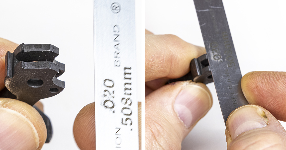
The hammer hooks should protrude .020 from the surface of the hammer. Use a .020 feeler gauge to check the hammer hook height. Hammer hooks that are longer than .020 will produce a trigger pull that feels excessively long and “creepy.” Hooks that are shorter than .020 are considered unsafe and the hammer should be replaced. The hammer and sear must fit together properly. This usually involves hand-fitting of the parts using specialized jigs. If any deformities are found with these components, it is best to consult a gunsmith for replacement.
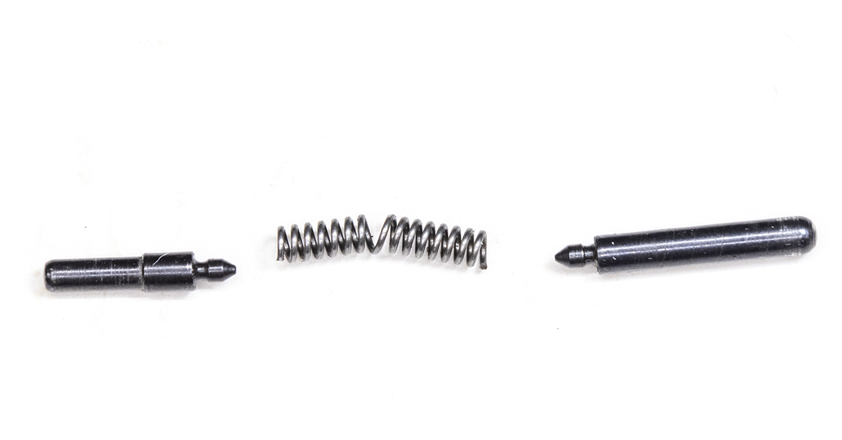
The plunger tube spring of this 1911 was found to be badly deformed. The spring was replaced with a Wolff plunger tube spring, part #26131. It is important to remember during reassembly that the longer detent (right) is the safety detent and will engage the thumb safety when properly installed.
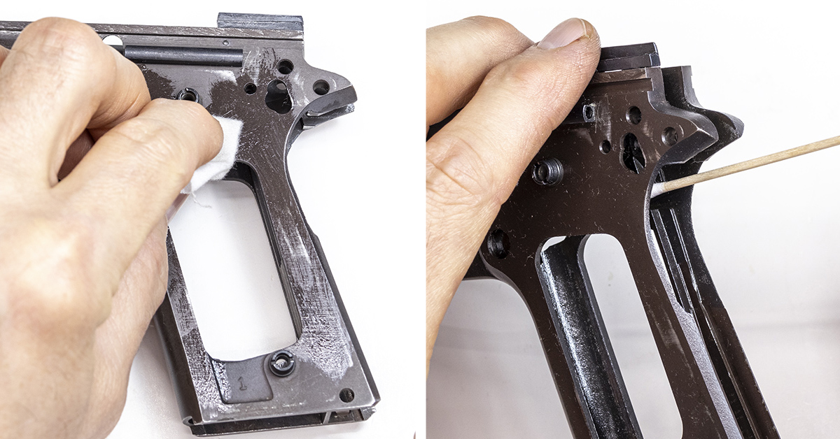
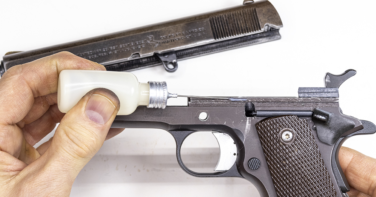
Apply a light coat of oil to all frame and frame components. These parts were thoroughly cleaned and degreased, removing all traces of oil. It is important that nothing is overlooked during this procedure. Use a cotton swab to apply a light coat of oil to all the recesses found within the frame.
For those that haven’t done this before, perhaps the most difficult part of reassembling the frame is that of reassembling the mainspring housing. The factory standard weight for the hammer spring is 23 lbs., and this spring must be compressed during reassembly. The old hammer spring in our 1911 was replaced with a new 23 lb. Wolff hammer spring, part #26223. Hammer springs of various weights are available for the 1911. While a lighter hammer spring can reduce trigger pull weight, a weaker hammer spring also means that the hammer will not be striking the firing pin with as much force as it did with the stronger spring. When doing a trigger job on a 1911, it is typically a little more involved than simply swapping out springs. While I find it wise to replace old worn springs when doing a project such as this, it is my advice to stay with the original factory weight springs.
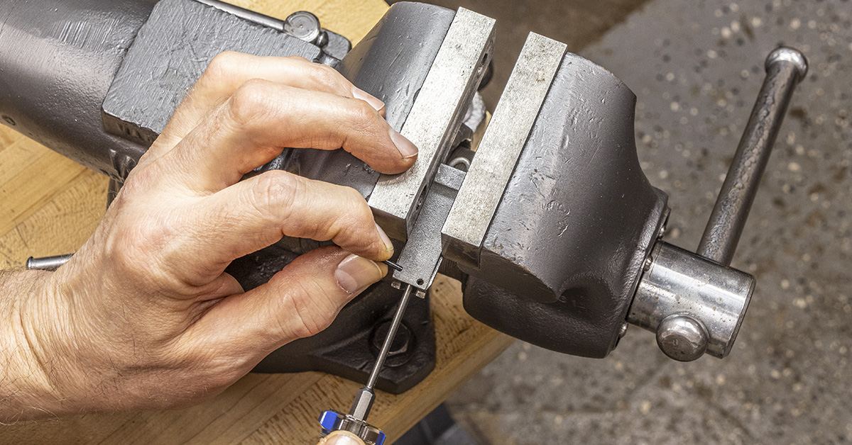
The easiest way that I have found to reassemble the mainspring housing is by securing the housing in a vise. There is a word of caution here. The jaws of my bench vise are ground smooth with no serrations. If the jaws of your vise are serrated, they will mar the housing. Some vise jaw pads made from ¼” thick plywood will provide ample protection to the workpiece. Lightly lubricate and then install the hammer spring assembly into the housing, using a small Allen head screwdriver since the shape of the Allen head driver will not mar the spring cap. Push inward on the spring cap, compressing the hammer spring assembly. Install the pin with the flared end up and then slowly release the spring tension.
Further reassembly of the frame is simply the reverse of disassembly. Lightly lubricate each part as you reassemble the frame. Begin by first installing the trigger and then the magazine release. The magazine release will hold the trigger within the frame as you install the remaining components.
Once the frame is reassembled, all that remains is installing the slide assembly onto the frame. All internal parts of the 1911 were lightly lubricated during reassembly. The only exception to “lightly lubricated” is that the guide rails of the receiver and the grooves of the slide are to be “well lubricated.” This begs the question, “How well is well?” This is best described as a coating of oil that is readily visible and easily spread with the fingers. Lubricate the slide grooves and the receiver rails, and then install the slide assembly onto the frame.
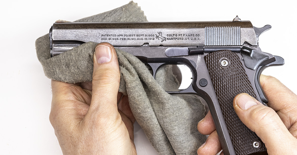
Use a soft cloth to wipe off any excessive oil. Our 1911 is now fully assembled, has new springs, is properly lubricated, and it is as clean as can be, ready for the range. Well…almost ready.
Stayed tuned for our third installment in this series where we take our freshened 1911 to the range and walk through several safety checks that should be performed prior to live-fire.