Those who are coming to recognize the no-fail simplicity of military-spec open sights on their conventional AR-15 rifles and carbines can easily make the conversion. Here’s how…
by Lou Patrick
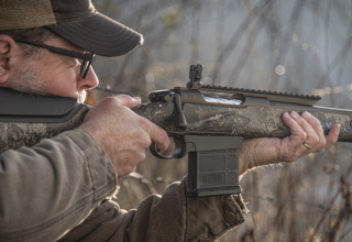
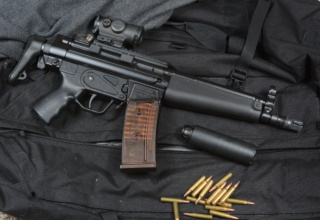
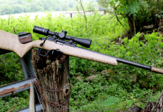
I decided it was time for my Rock River Arms 9mm carbine to get a new look. I’ve had this carbine for a few years now, and it has served me well. The same can be said for the TRUGLO micro red dot sight as well as the XS Sights tactical flip-up sights.
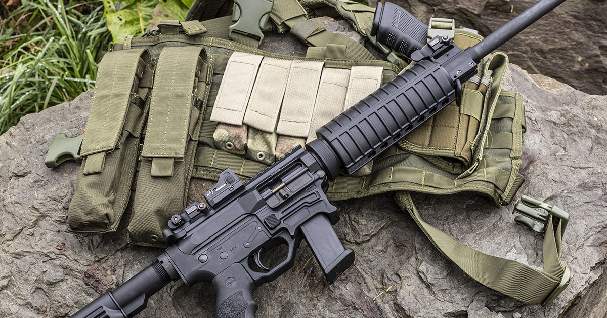
While this has proven to be an accurate, reliable, and fun-to-shoot platform, the problem for me, in a way, has been that this carbine looks similar to my 5.56 carbine. In short, I don’t like confusion (momentarily as it may be) when reaching into my gun vault. So, I decided it was high time to color code the carbines. The 9mm would get a new set of furniture to put an end to the carbine confusion. Along with the furniture swap, I also decided to make the switch to the “old school” USGI style iron sights.
Conventional wisdom might consider this a step back in sighting systems, as the red dot is fast to acquire and easy enough to place on target and the XS backup sights are ready should anything go wrong with the red dot. That begs the question, “Why make the switch?”
For me, I simply can’t get past the need to turn my carbine “on.” This is also combined with the carbine being battery-dependent. After all, a dead battery equates to zero function of what is supposed to be the primary sight. I’ve often wondered how many people have gone to the range expecting a fun afternoon of shooting, only to find upon arrival that their batteries are dead and they are without a spare. Of course, proper planning would eliminate this problem, but that is yet another thing to keep track of. I come from a time when once the round is chambered, you need only to move the safety selector to the fire position, align the sights on target, and fire. No “on/off” switch, brightness control, or batteries to be concerned with. In my shooting experience, which now spans five decades and includes military service, iron sights have never let me down nor have I ever needed a “back-up” sighting system.
Should you also have the desire to return your AR-platform rifle/carbine to the simplicity and rugged dependability of the “old school” USGI style iron sights, the procedure described here makes the conversion easy enough that most DIYers can handle it with basic hand tools, resulting in a quality installation that will serve them well for years to come.
As always, before working on your firearm, ensure that it is unloaded and that no ammunition is present in the workplace.
Furniture is simply a reference to the stock, pistol grip, and handguard, and replacing the furniture is easy enough on the AR-15. It does, though, require proper planning. It is, embarrassingly, in the planning stage that I initially failed in this project. I took it for granted that the receiver extension (commonly referred to as the buffer tube) on the 9mm carbine was MILSPEC.
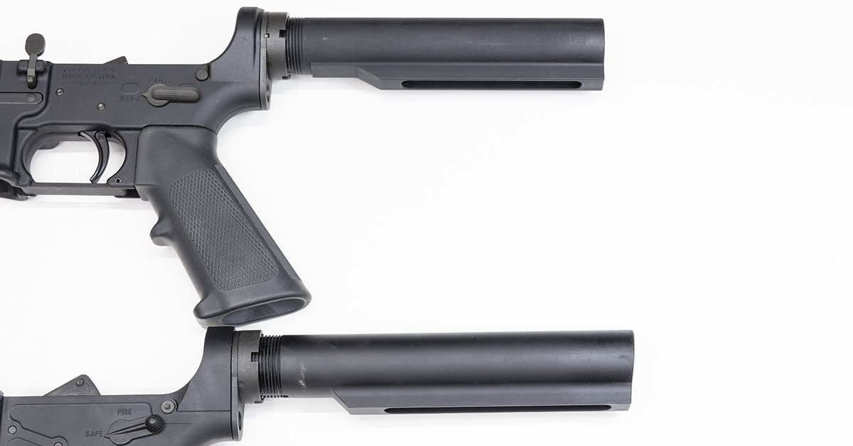
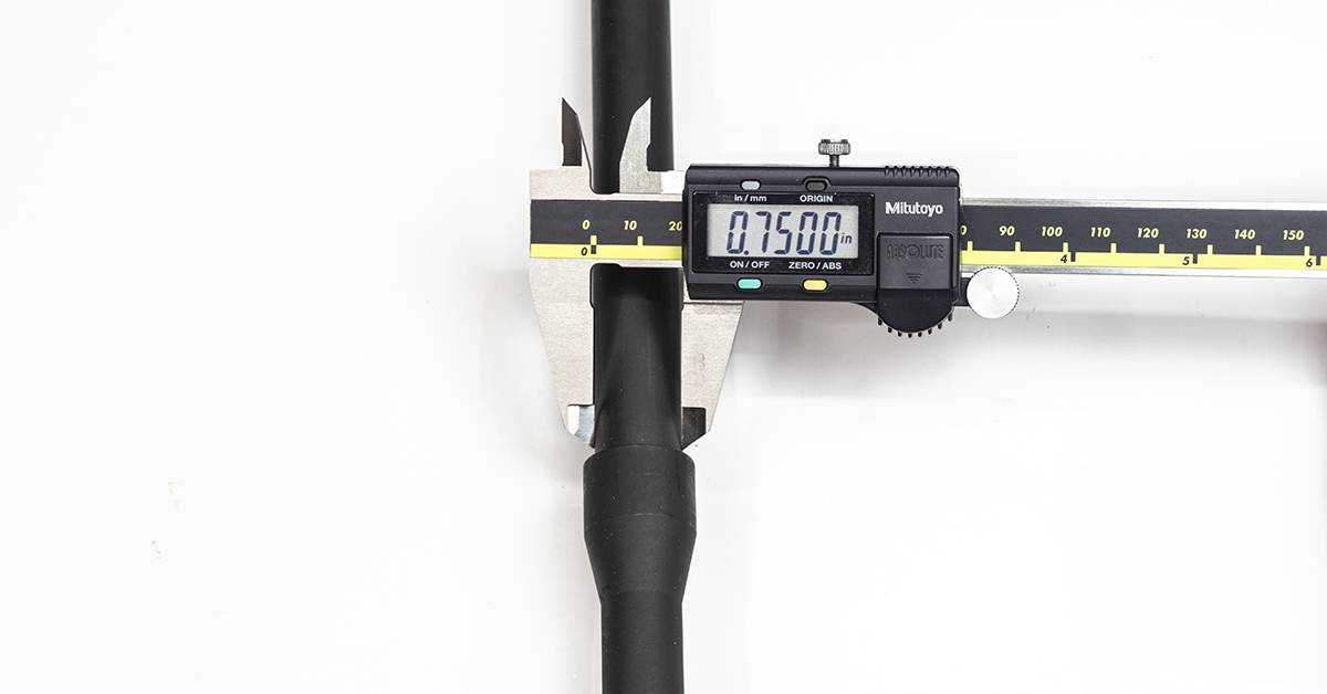
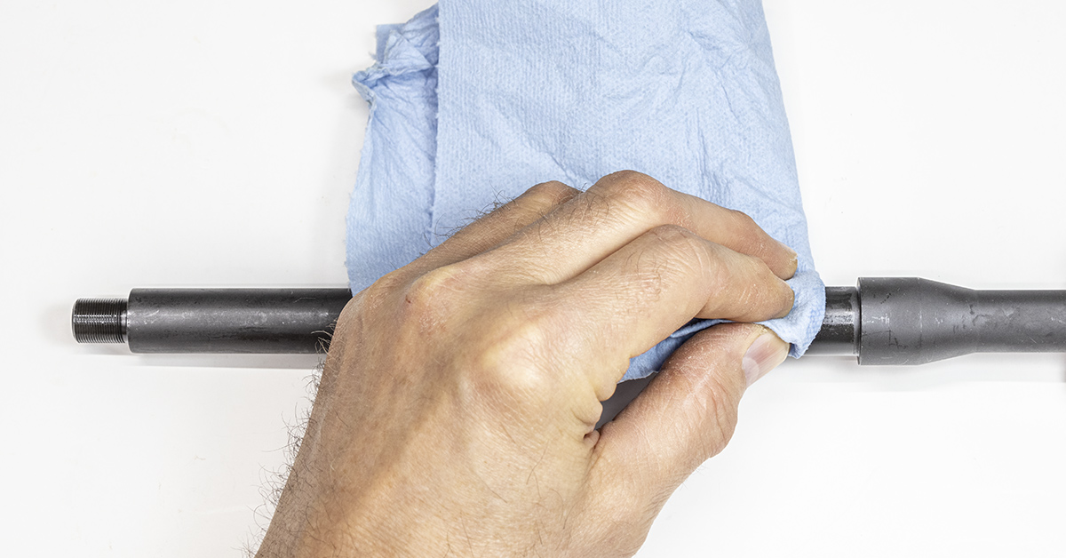
There are two different sizes of buffer tubes found on the AR carbine. One is dimensionally made to military specifications and is referred to as MILSPEC. The other is the “commercial tube” that is not produced to military specifications and is somewhat larger in diameter. The top tube pictured above is the MILSPEC tube. Look closely at the end of the tube. It is flat. The end of the commercial tube, pictured below it, is angled. While I cannot guarantee this is always the case, in my experience, it is the norm and a good indicator as to what size tube is on your carbine.
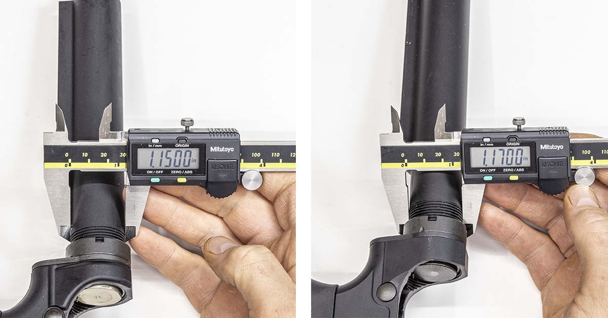
The only way to be certain which tube you have is to measure its diameter. The MILSPEC tube (left) will measure 1.15 inches in diameter, with the commercial tube (right) measuring 1.17 inches in diameter. A buttstock that is sized for the commercial tube will fit on the MILSPEC tube, although it will be excessively loose. The Mil-Spec buttstock will not fit onto the commercial tube. It is here that I discovered my mistake, having not taken the time to measure the buffer tube and confirm its size. To keep the project rolling, a quick call to ATR Performance in Fairmont, WV, solved the problem.
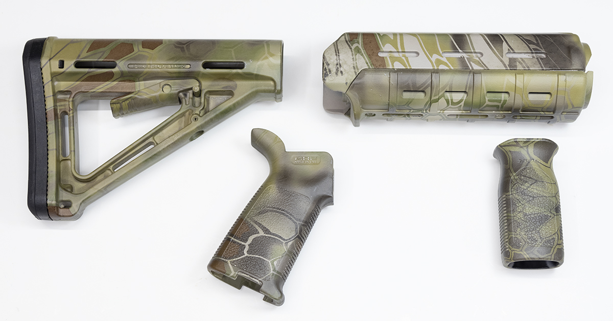
The stock set that I found at ATR consists of all Magpul components that have had a camouflage finish applied by Matrix Industries.
The gas block/front sight mounting surface of the barrel can vary according to barrel contour and manufacturer. Measure this surface prior to purchasing your front sight assembly.
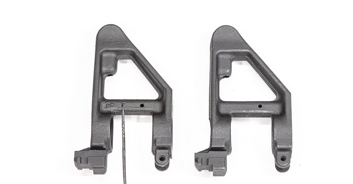
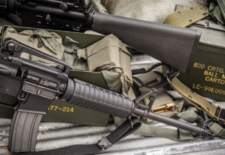
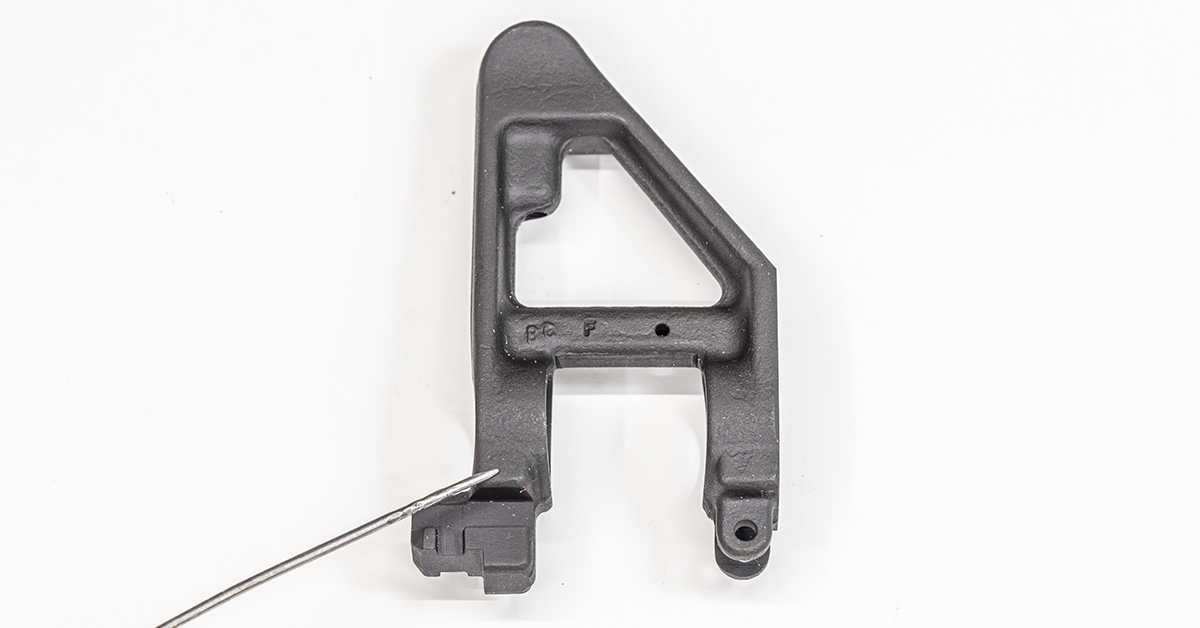
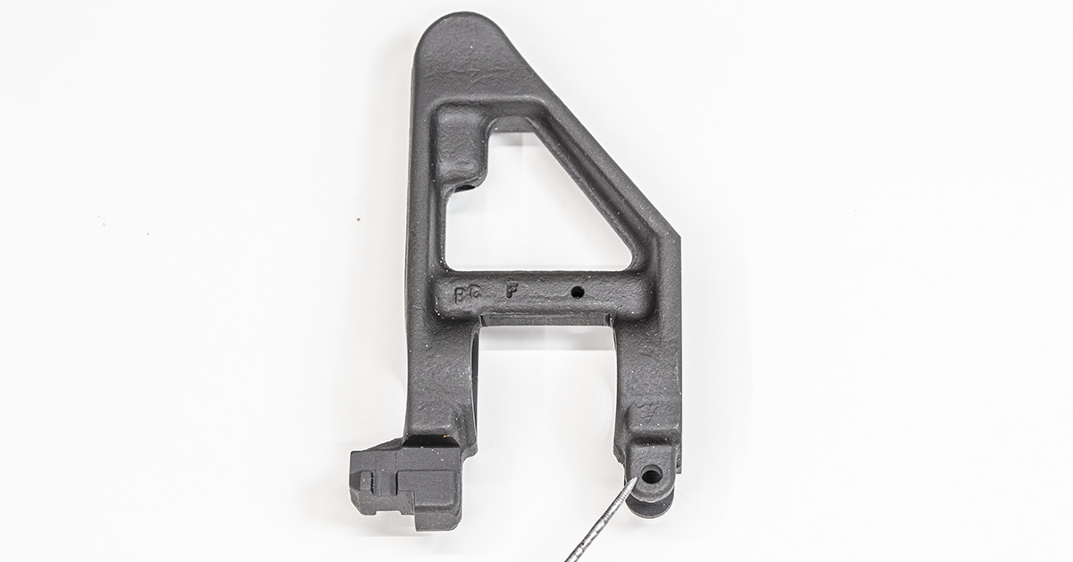
The USGI front sight is available in two different varieties. They may look identical, but the one marked “F” is for use with flat top receivers that use a detachable carry handle/rear sight assembly.
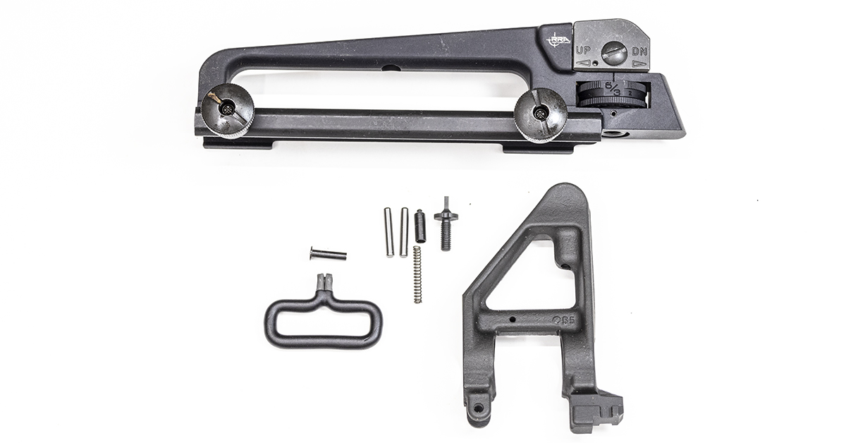
The carry handle and front sight components I selected are MILSPEC parts from Rock River Arms.
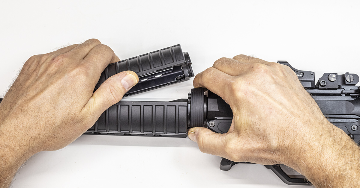
Remove the handguard by pulling the delta ring back and lifting the top handguard up at an angle as pictured. Remove the bottom handguard in similar fashion. Next, separate the upper and lower receiver assemblies.
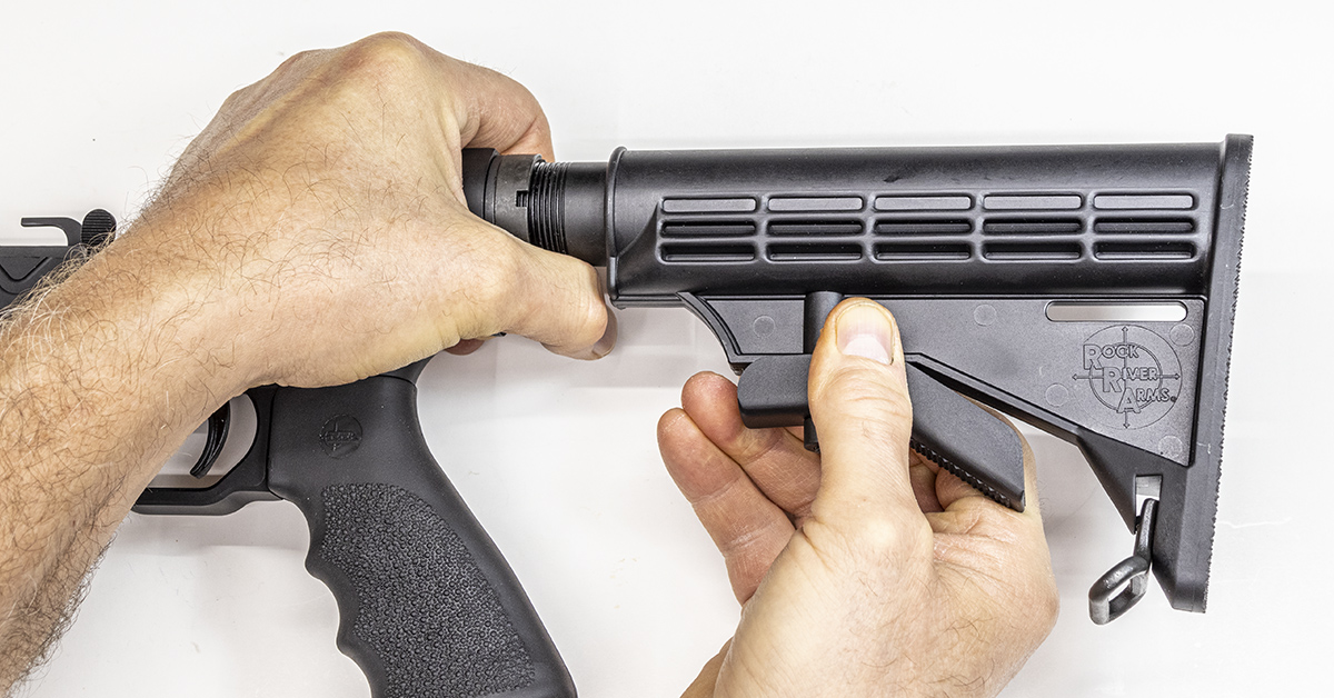
Pull down on the stock latch. While holding the latch in its downward position, slide the stock off the buffer tube. Next, remove the screw that attaches the pistol grip to the lower receiver and remove the pistol grip.
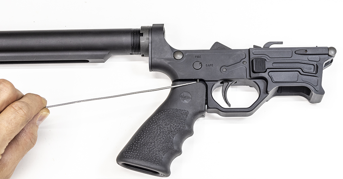
Be careful as you remove the grip because it captures the safety selector’s detent and spring. Once the grip is removed, these components are free to fall out of the receiver. If they happen to fall out, the detent goes into the receiver pointed end first, followed by the spring. The bottom portion of the spring seats in a hole within the pistol grip.
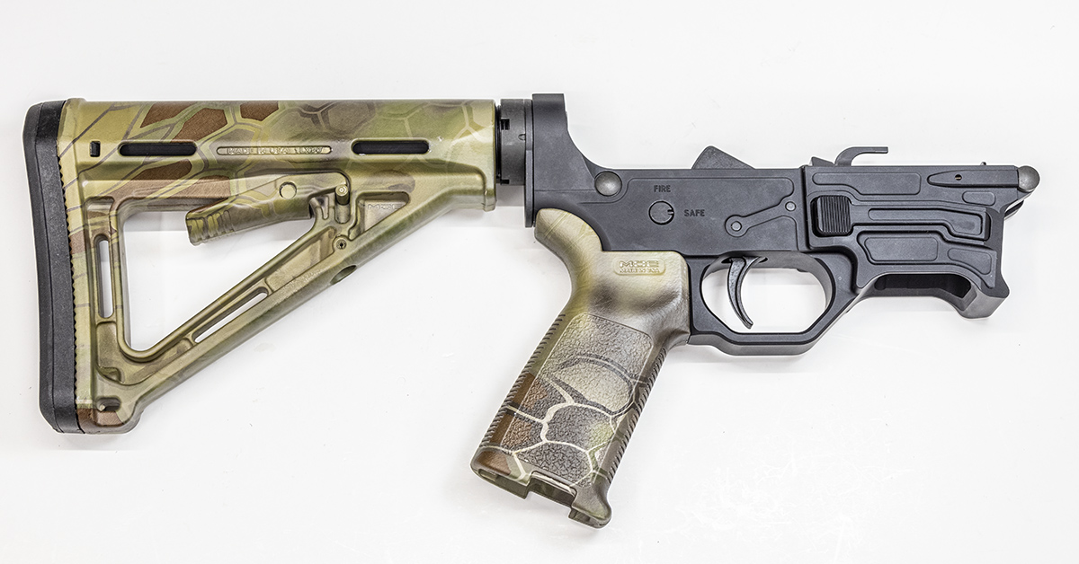
Installation of the new stock and pistol grip is the reverse of disassembly. Just a few minutes into the project and the carbine is already looking better!
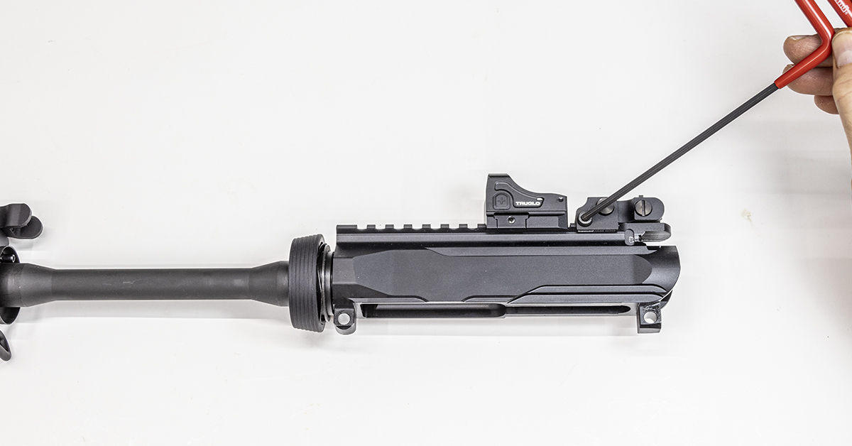
Remove the bolt carrier group and charging handle, along with the current sighting system.
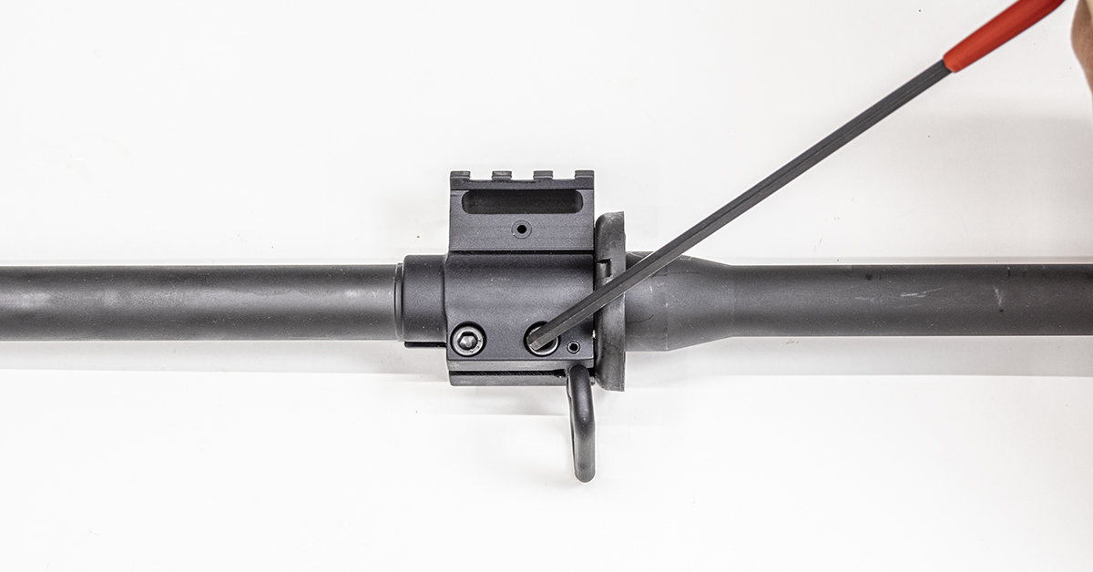
Loosen the gas block screws.
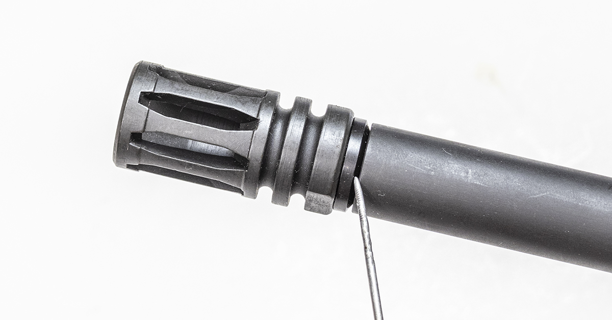
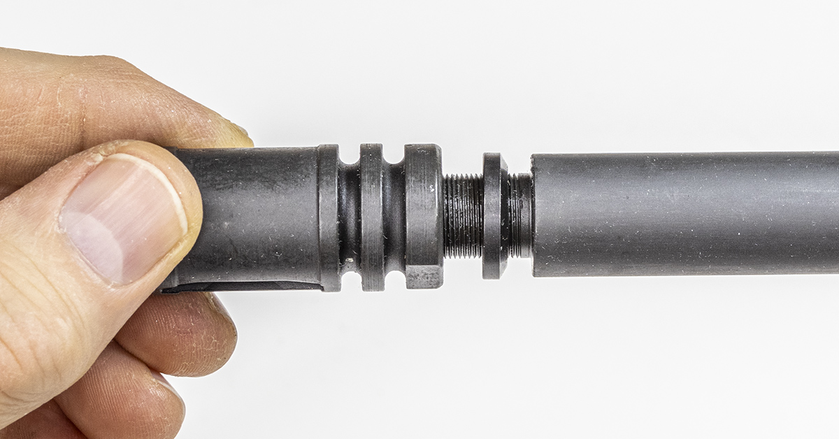
The crush washer is a separate part from the flash suppressor. Note how it is installed on the barrel. The tapered end goes towards the barrel shoulder during reinstallation.
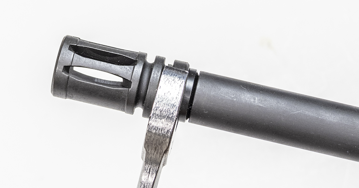
Do not vise on the receiver to remove the flash suppressor. Instead, hold the barrel in padded vise jaws and, using a ¾-inch wrench, remove the flash hider by turning it counterclockwise.
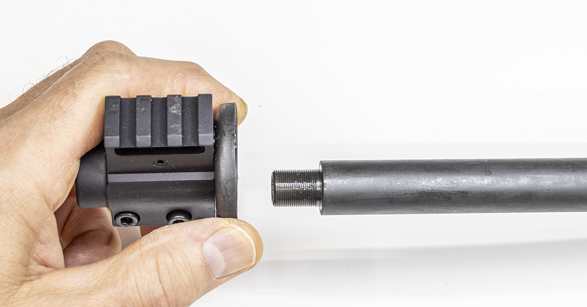
With the flash suppressor removed, slide the gas block and end cap assembly forward and off the barrel.
The 9mm carbine, being operated by what is known as a blow-back system, does not require the use of a gas tube, which would normally be found on a 5.56 carbine. The round component between my thumb and index finger is the end cap. The end cap provides the forward mounting surface for the hand guards. The gas tube serves double duty, as it also provides a means to locate the end cap and keep it from rotating around the barrel. In the absence of the gas tube, the 9mm carbine uses a roll pin to secure the end cap in place. Lift upward on the end cap to remove it from the gas block.
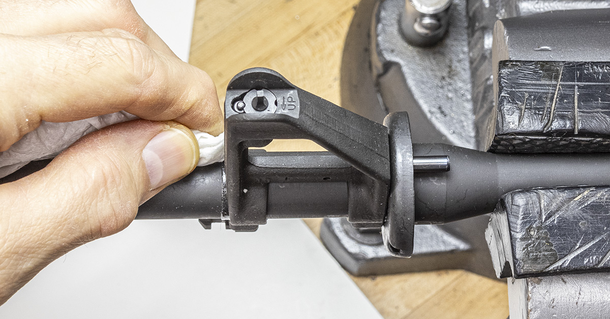
Thoroughly clean and degrease the front sight mounting surface of the barrel.
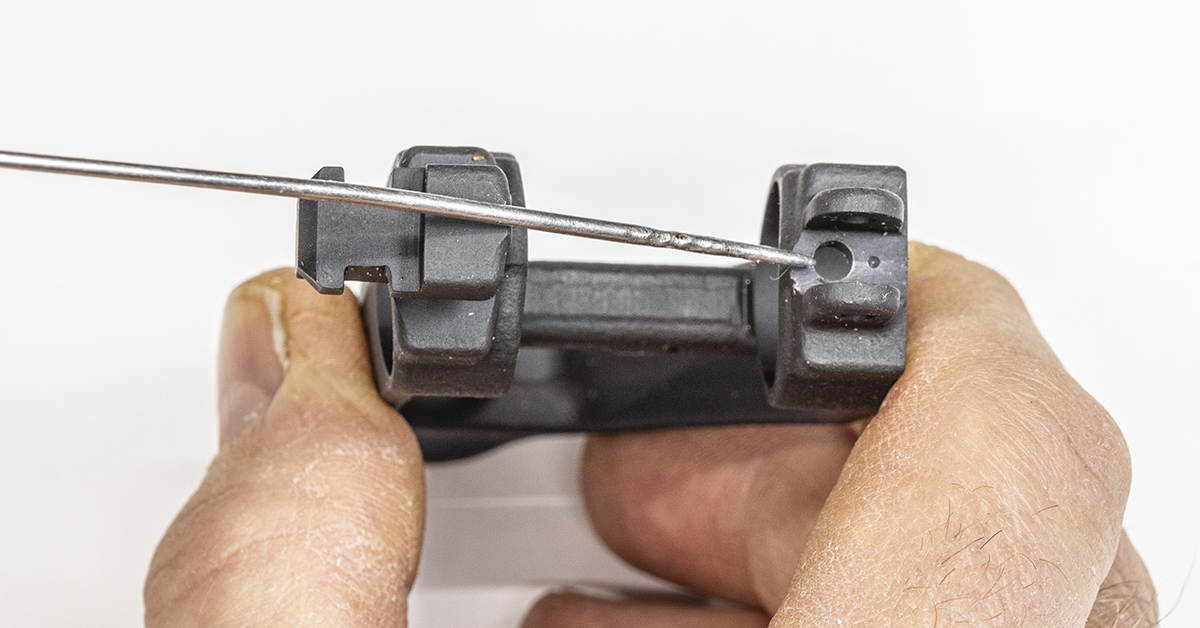
Factory installed front sight assemblies were originally secured to the barrel using two taper pins. One pin was installed on each of the flat spots found on the front sight assembly as indicated. While this is the most secure way to attach the front sight to the barrel, over the years, this method has given way to the use of dowel pins, roll pins, and set screws. My preference is to use taper pins or dowel pins. The problem is, this method poses some difficulties for the average DIY installation. The first is expense. When using either of these pins, the holes must first be drilled (undersize) and then reamed to the proper size with the appropriate reamer. Whether we are speaking of reaming a tapered hole or a straight hole, either reamer will cost more than a tap. The use of roll pins does away with the need for a reamed hole, but it also has the same problem of properly locating and holding the front sight onto the barrel while drilling the holes. While this is not impossible to do for the savvy DIYer, it is a concern because once its drilled, it’s drilled — straight or not. Drilling and reaming the front sight for pin installation also dedicates the front sight to be used only on that barrel. It also means that should you wish to change back to a different sighting system in the future, you may be left with some unsightly holes in your barrel. For these reasons, it is my advice for the DIYer to attach the front sight using a set screw — and you don’t have to purchase an aftermarket sight assembly to do it.
The USGI front sight assembly is easily converted to set screw mounting by using the hole that already exists in the sight. This hole is present as part of the manufacturing process, as it provides access to drill the gas port. With the front sight already being a precise fit to the barrel — so precise, in fact, that it often requires a few taps from a hammer to remove — one set screw installed here will firmly hold it in place.
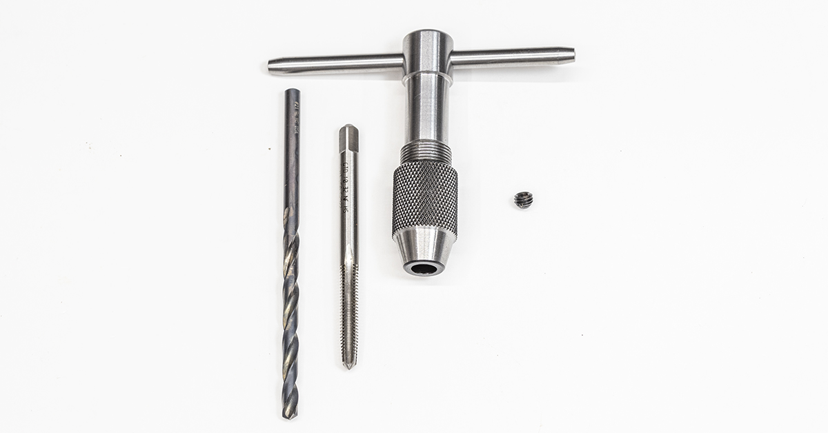
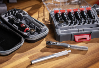
To make the conversion, you will need a #21 drill bit, a 10-32 taper tap, tap handle, and set screw. Taps are commonly produced with three different chamfers towards the cutting point. These chamfers are referred to as taper, plug, and bottoming. The taper chamfer is the best choice for this project since it allows the tap to be more easily aligned within the hole as the cutting action begins. Taps and drill bits are also made from different types of material. They must also be harder than the material being cut. With the front sight assembly being made from a rather hard material, a tap and drill made from high-speed steel (HSS) is the best choice for this project.
McMaster Carr part numbers: HSS Taper tap 2522A759; HSS #21 drill 2901A194.
It is important to use a cup point set screw since the shape of the point will engage into the barrel, firmly locking the sight assembly in place.
McMaster Carr part number 91375A436.
The two tabs on the rear of the sight assembly are for mounting the front sling swivel. The conversion to set screw mounting can be accomplished with these tabs in place; however, I begin by removing these tabs since I will be using a Magpul quick release sling attachment point mounted to the front handguard.
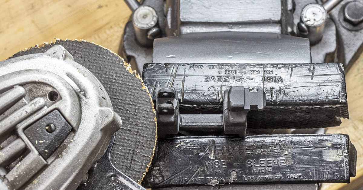
Holding the front sight in padded vise jaws, use an angle grinder to remove the front sling mounting tabs, cutting them off as close as you can without damaging the sight assembly.
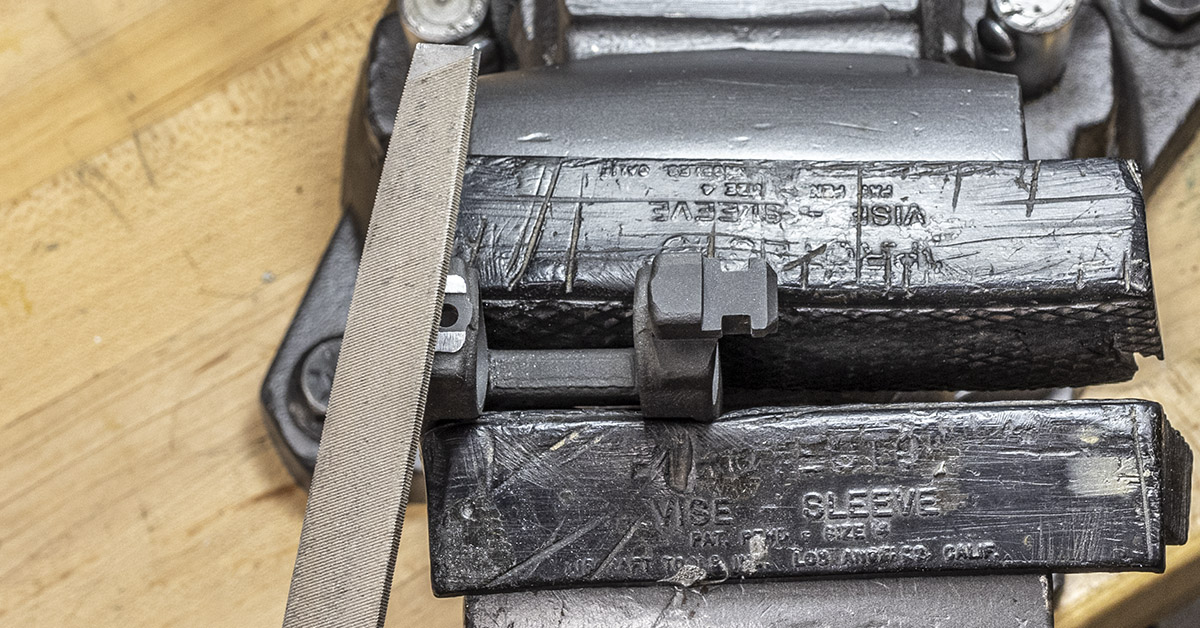
Next, file the tabs to the final height.
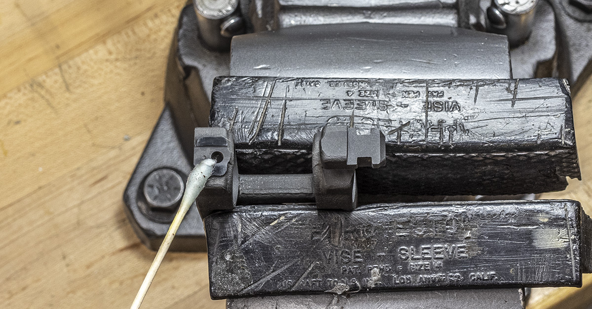
Apply Birchwood Casey Perma Blue to provide color and prevent rust.
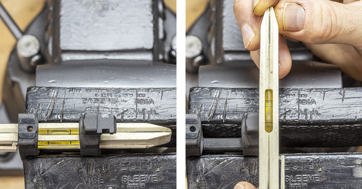
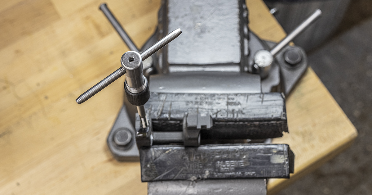
Prior to drilling the hole for tapping, position the sight assembly as level as possible in the vise.
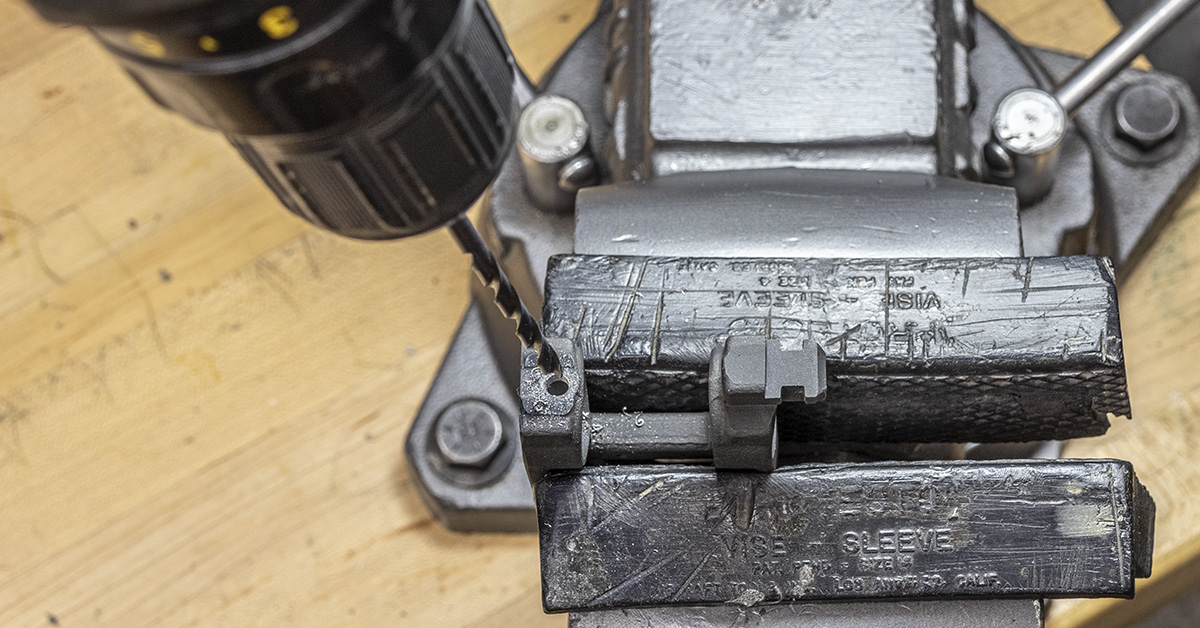
The hole that is present is similar in size to that which is needed for tapping. There is not much material that needs to be removed. Using a hand drill and holding it as straight as possible, drill the hole using the #21 drill bit. While drilling, allow the drill bit to center and follow the already established hole. This is going to be its natural tendency.
Clean the hole of all chips from the drilling operation and lubricate the tap and hole using dark (high sulfur content) thread cutting oil. The same oil used when threading black iron gas pipes works great. Start the tap slowly, allowing the taper chamfer on the tap to center itself in the hole.
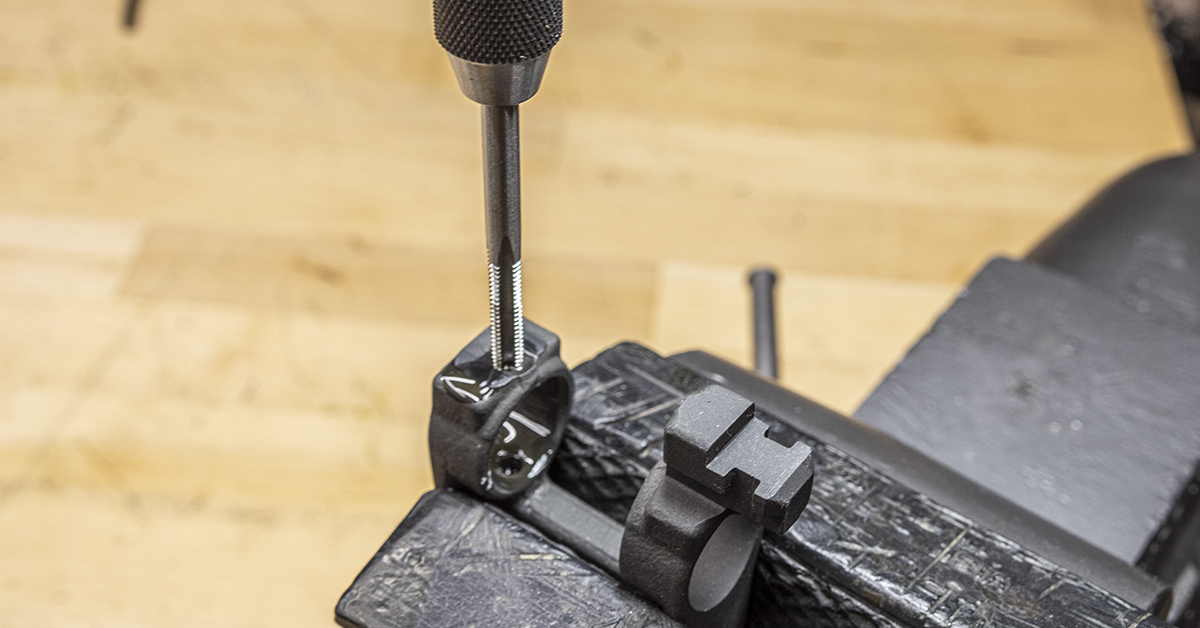
Once the tap begins to cut, you may feel that it is binding in the hole. This is a natural part of the cutting action. Once you feel that the tap is binding, turn it in the opposite direction about a ¼ turn. This will break the chip and allow you to continue to cut the thread. You will need to “break the chip” a few times as you thread the hole. Continue working the tap through the hole until it become easy to turn. This will ensure that you have worked the tap into the hole past the tap’s chamfer and that the hole is threaded to full diameter.
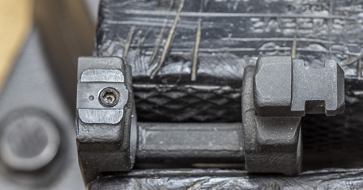
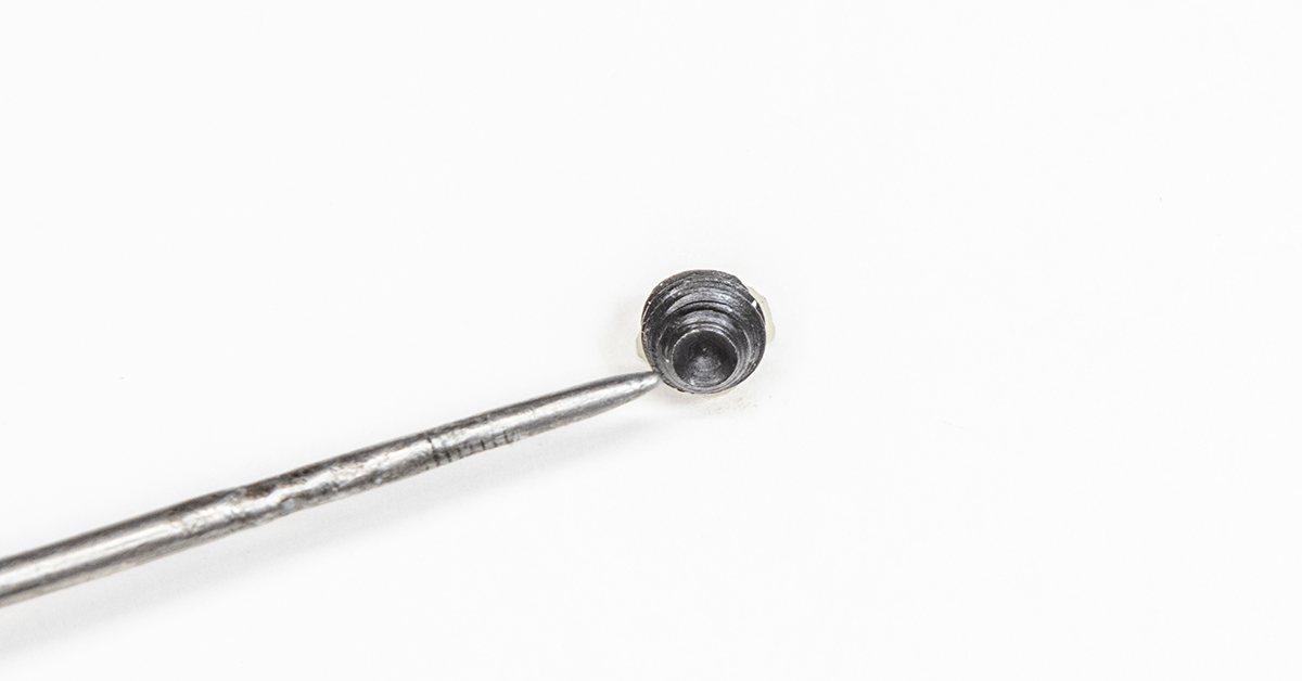
Remove the tap, clean the workpiece using denatured alcohol to remove all traces of cutting oil, and then install the set screw. Check for proper fitment. The screw should easily turn completely through the hole.
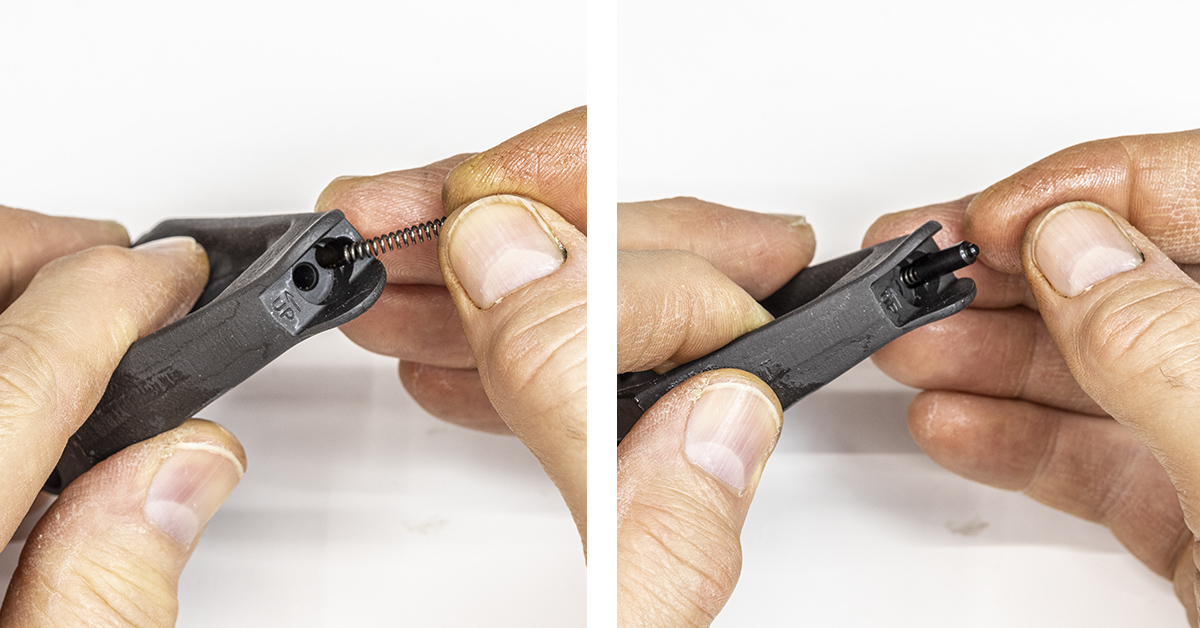
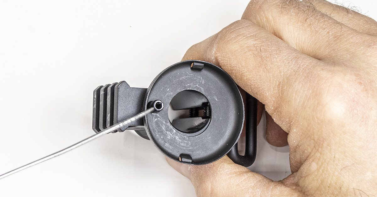
Lightly lubricate and install the front sight detent spring and detent.
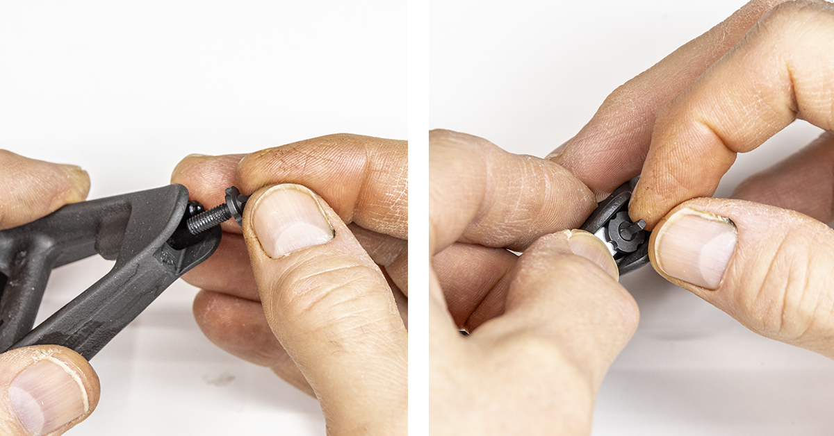
Lightly lubricate and install the front sight post by turning it clockwise into the housing. You will need to hold the detent down as you do this. A tool can be fashioned from one of the thicker leaves found on a mechanic’s feeler gauge. Once you get it started, switch to an AR-15 front sight tool.
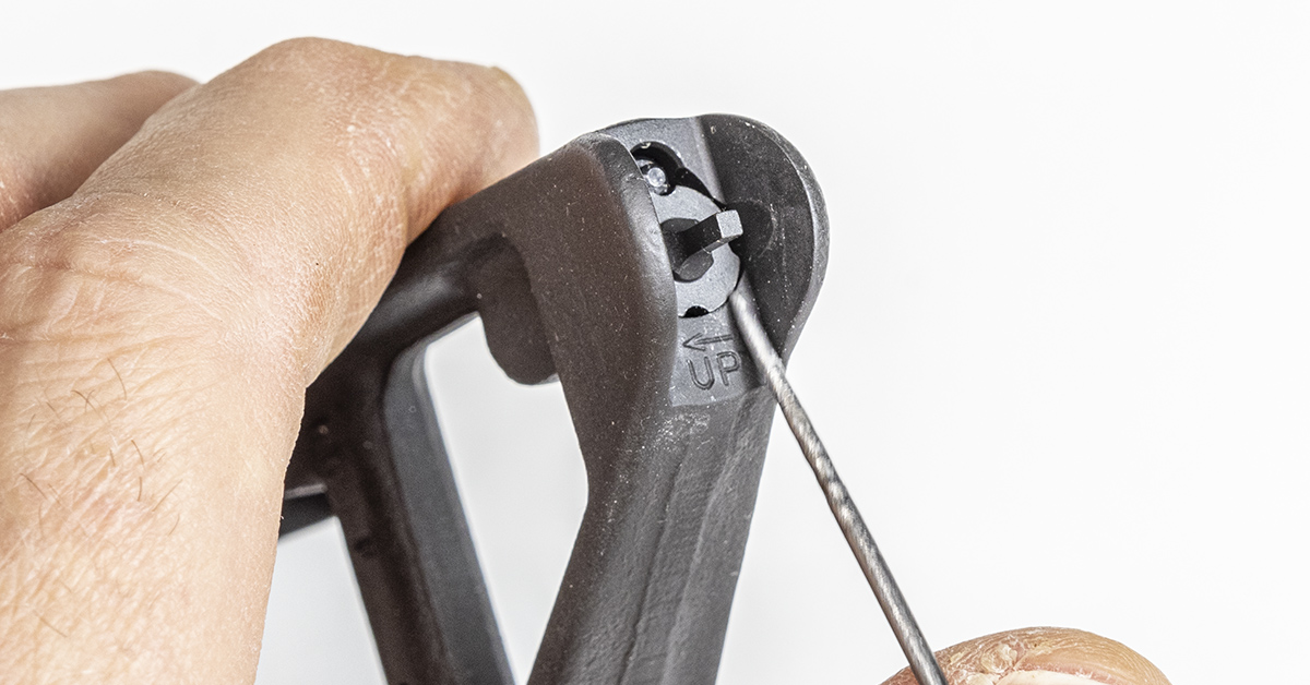
Thread the front sight into the housing until the base of the front sight is level with the housing. This is its mechanical zero.
Secure the barrel in padded vise jaws with the top of the receiver level.
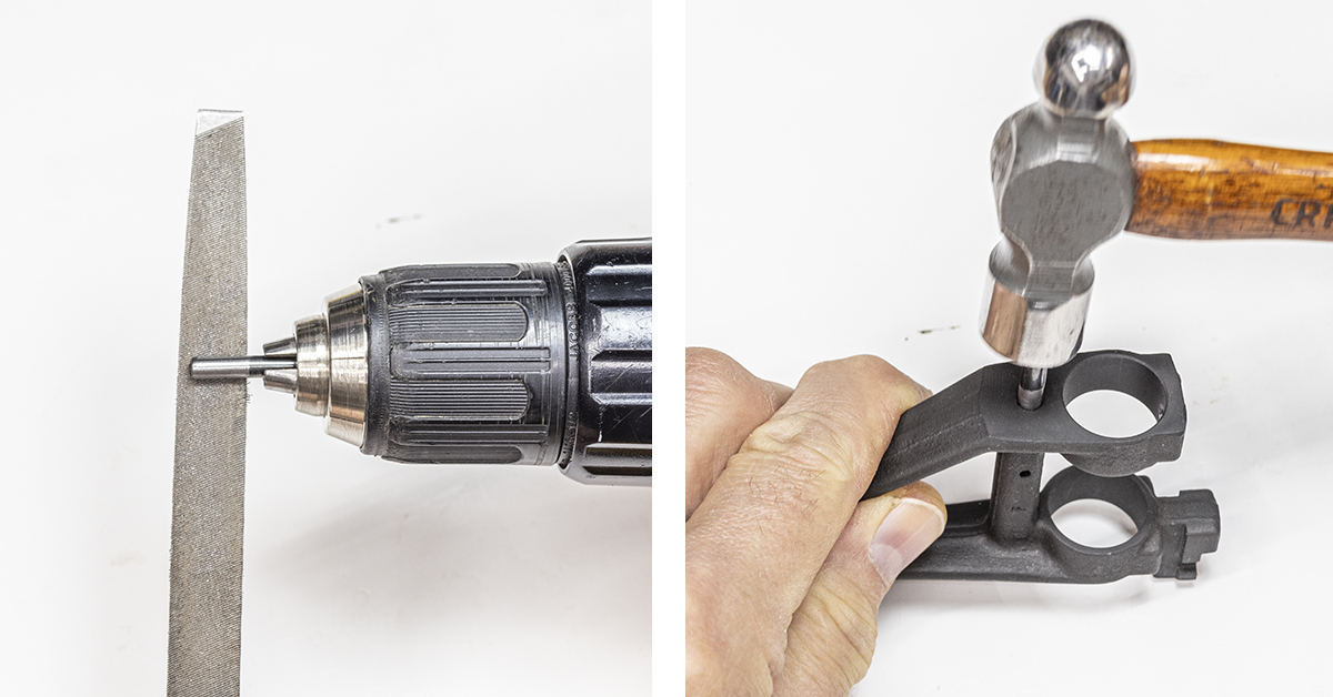
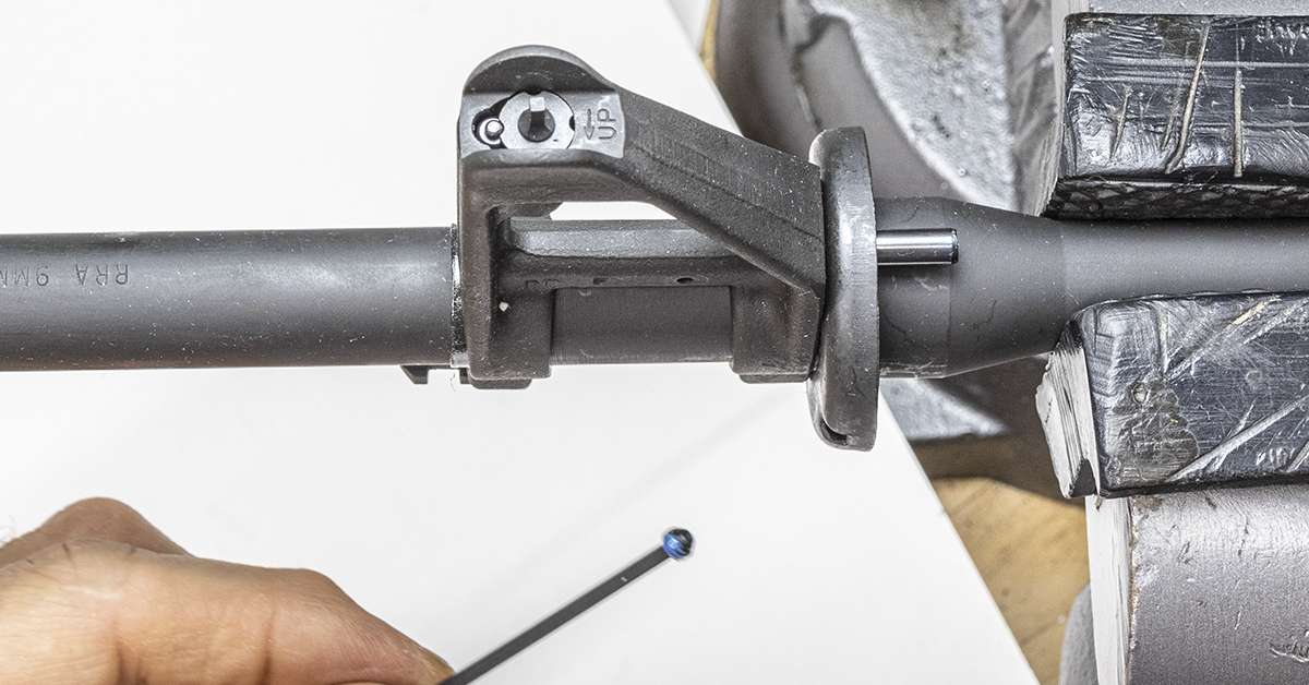
I was unable to remove the original roll pin from the gas block without damaging it. A one-inch section cut from an old gas tube would work to locate the end cap; however, I’m not willing to waste a gas tube for this function. A roll pin is a better choice in my opinion. As luck would have it, a 5/32-inch roll pin is too small and a 3/16-inch pin is too large. So, I took a one-inch long 3/16-inch diameter roll pin and used a hand drill to spin it against a file to reduce its diameter. You don’t have to remove much material. Once the pin starts to go into the hole with finger pressure, install the pin using a small hammer.
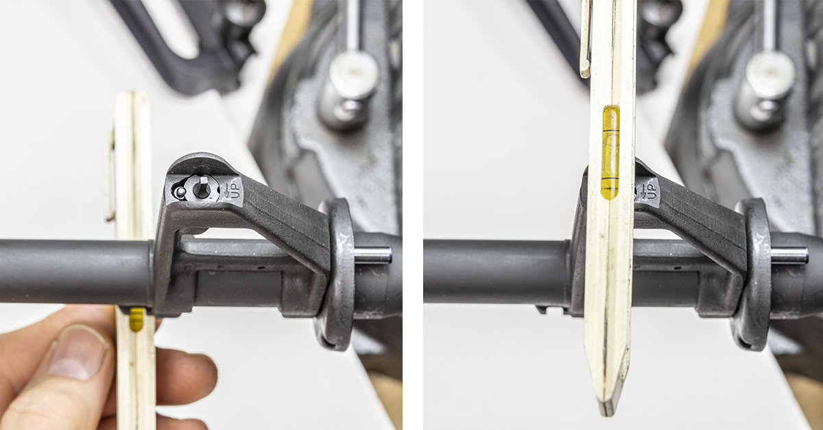
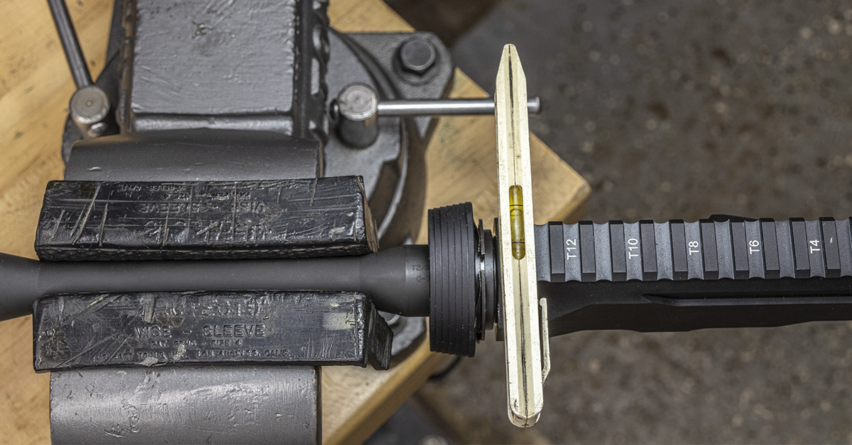
Next, check fitment. Install the front sight/end cap assembly onto the barrel with the end cap fully seated against the barrel shoulder. Use a small level across the bottom flat of the bayonet lug and across the top of the front sight. Once you are satisfied that the front sight is level, move to the rear of the receiver and look closely across the top of the receiver flat and the front sight. The front sight should be vertical. If not, adjust the position of the front sight as needed. In my experience, further adjustment is seldom needed. Do not tighten the set screw at this time. This step is done just to give us an idea of what we must work with and what will be needed to get the front sight aligned vertically. When the set screw is tightened. it will engage the barrel, causing a small imprint of the cup point to be made on the surface of the barrel. Once engagement has been made, it will always want to go back to this position, making small adjustments difficult.
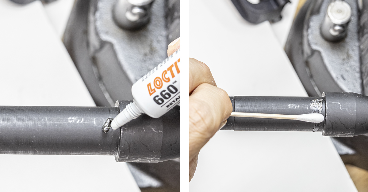
Remove the front sight assembly from the barrel and apply Loctite 660 retaining compound to the front sight’s rear mounting surface on the barrel. Put an even coat completely around the barrel. Do not apply it to the shoulder. If you are working on a firearm that has a gas port, ensure that the retaining compound does not find its way into the gas port.
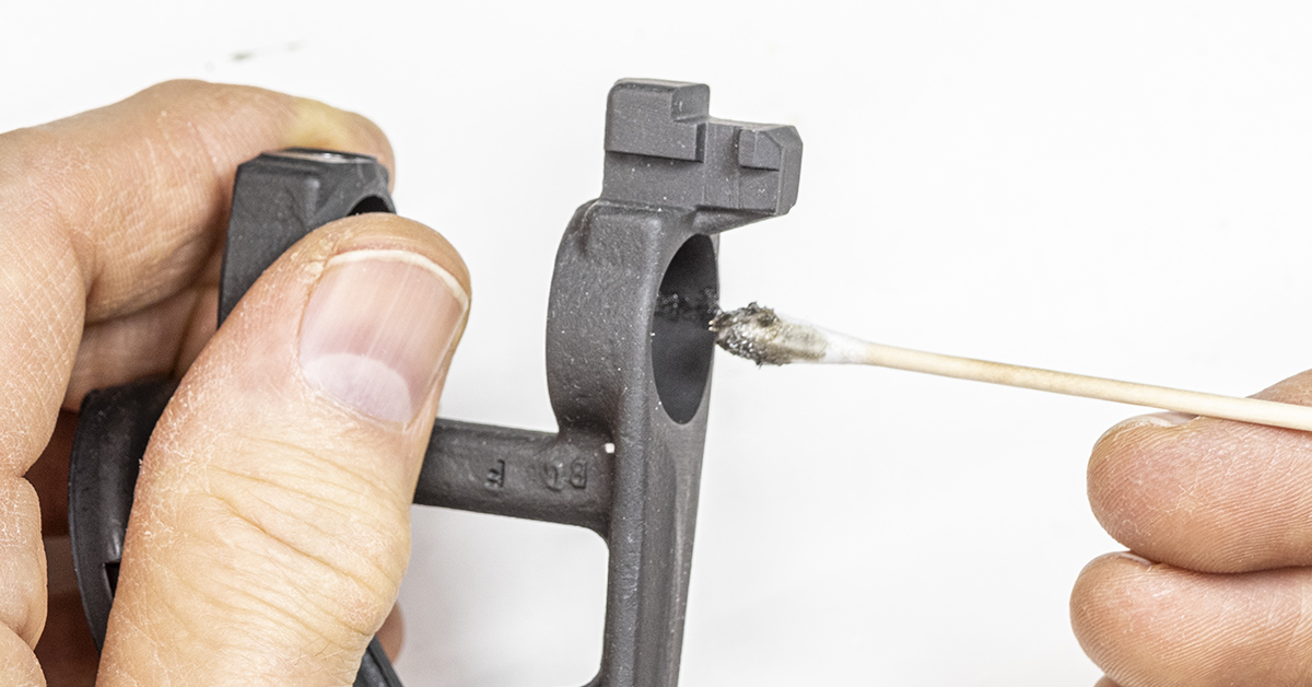
Use denatured alcohol to degrease the internal mounting surfaces of the front sight and the set screw. Apply Loctite 660 retaining compound inside the forward mounting surface of the front sight as shown. Loctite 660 retaining compound is designed to provide additional strength/repair of press-fit joints. It can fill gaps reliably up to .020 inches, has an operating temperature of -65° to 300° F, and has a shear strength of 3,335 psi. While the addition of Loctite 660 is probably not a necessity for this project, it is easy enough to apply and provides yet another means of securing the front sight while simultaneously keeping old man Murphy at bay.
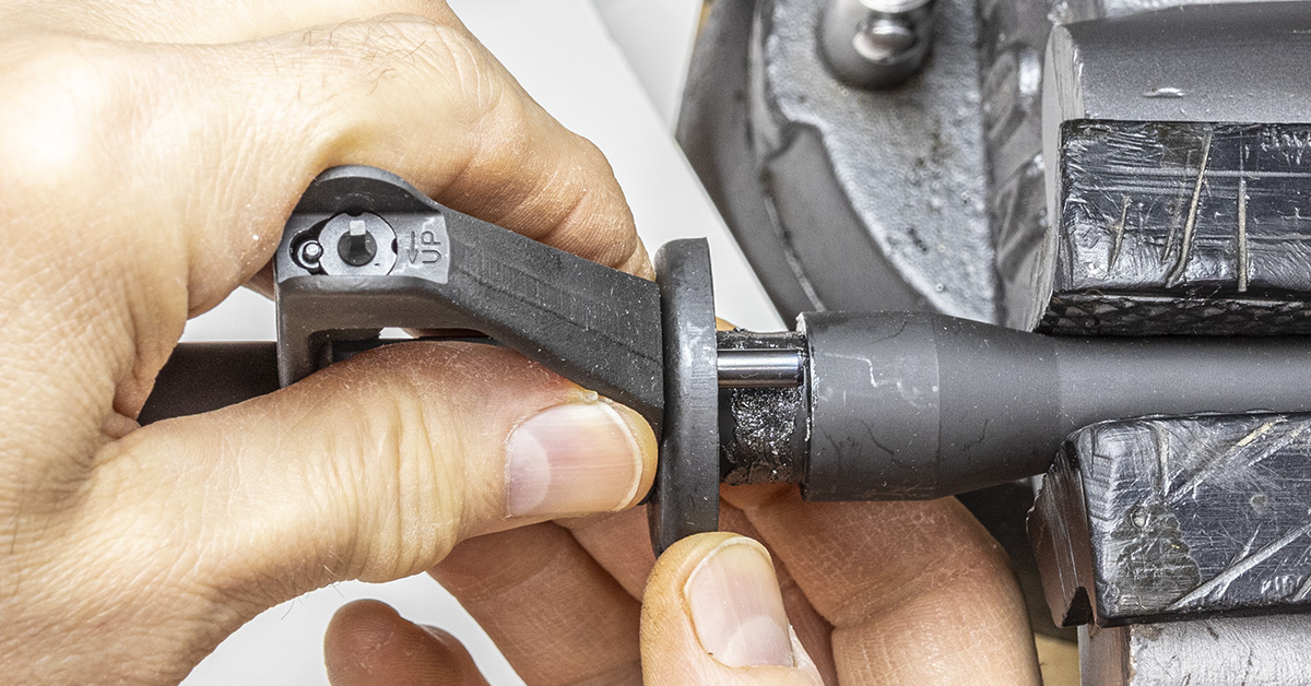
Carefully slide the front sight/end cap assembly onto the barrel. Ensure that the end cap is seated firmly against the barrel shoulder.
Apply blue Loctite 242 to the set screw. Install the set screw loosely. DO NOT engage the barrel at this time. Align the sight vertically as previously performed. Once aligned, then tighten the set screw.
Remove any excess Loctite 660 and allow to cure at room temperature for two hours.
Install the crush washer with the tapered end towards the barrel shoulder. Install the flash suppressor, turning it finger tight until it stops.
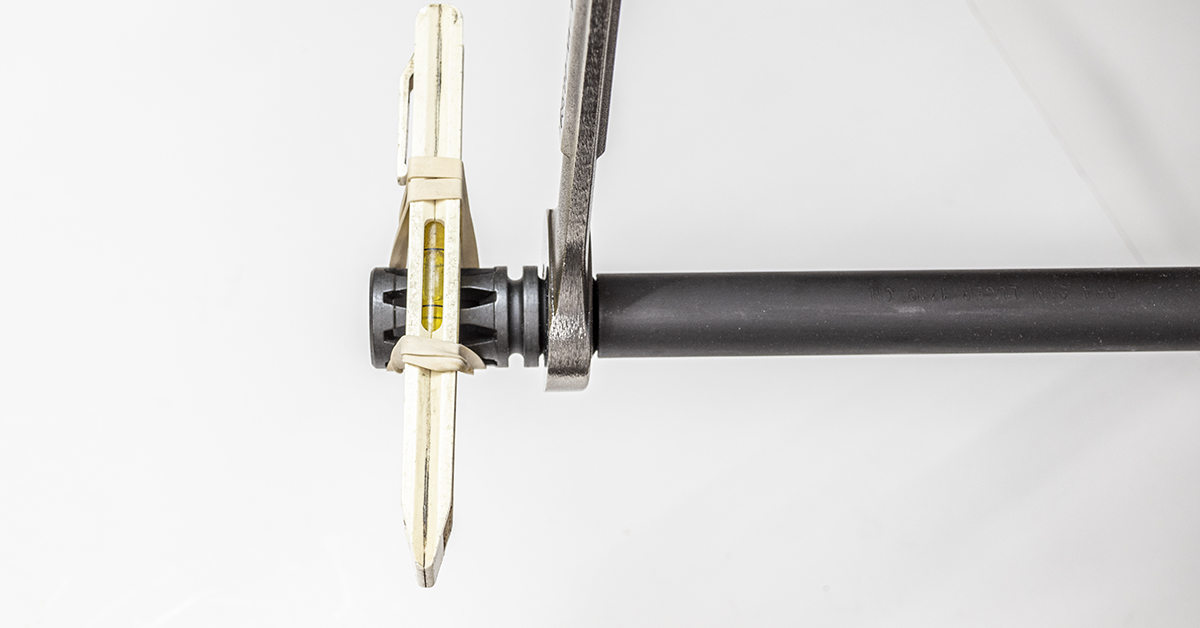
The flash suppressor is to be tightened to 15-20 ft/lbs of torque. In the absence of a torque wrench and/or when working on a project such as this (meaning the crush washer has already been crushed once when it was installed onto the barrel), it has been my experience that screwing the flash suppressor to finger tightness and then using a rubber band to hold a small level across the top of the center slot, you can use a wrench to tighten the flash suppressor to “level” and achieve proper alignment and sufficient torque. You can also just install a new crush washer.
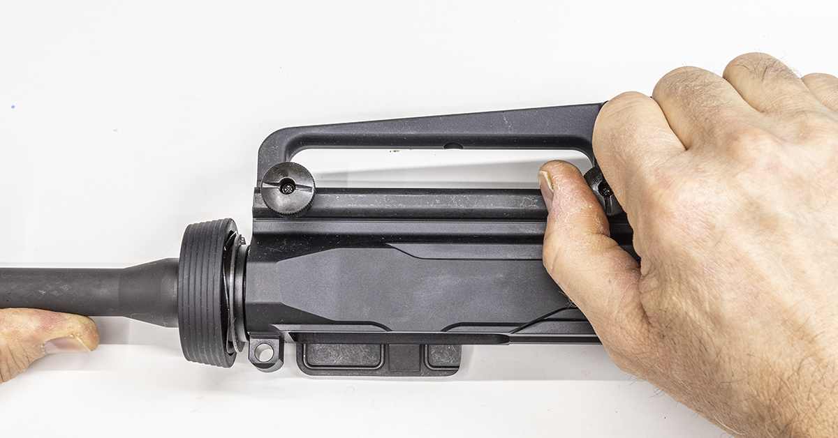
Install the carry handle onto the lower receiver with the carry handle’s front cross bolt centered in the first slot (closest to delta ring) on the receiver. The carry handle nuts are then tightened by hand only, with the tightness checked daily during use. Properly installed, the handle will stay tight. DO NOT use a screwdriver to tighten these nuts!
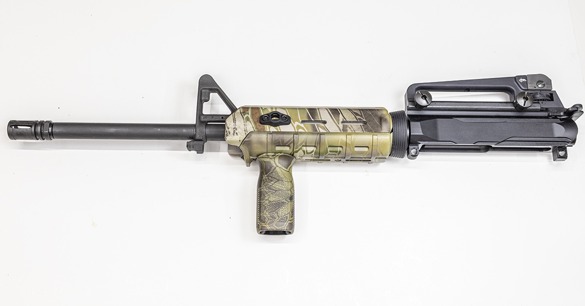
Install the hand guard, vertical grip, and sling attachment points according to the manufacturer’s instructions.
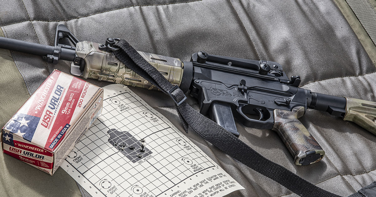
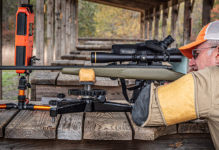
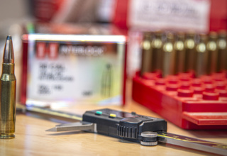
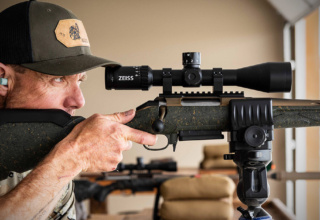
I zeroed the carbine at 25 meters using a U.S. Military M4 zeroing target and Winchester 124-grain 9mm NATO ammunition. The use of the military target provides the grid needed to make accurate and easy sights adjustments.
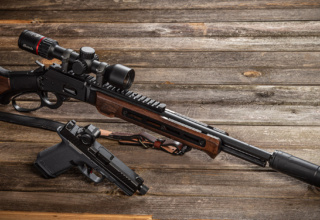
For me, this has been a worthwhile project. The carbine performed flawlessly on the range and is now easily recognizable from the other 5.56 carbines in my safe. Best of all, I don’t have to turn anything on to shoot!