Timney belted a home run when the company introduced its first precision trigger for the GLOCK. Now Timney scores another run with the Ultimate Builder’s Kit.
by Rob Reaser
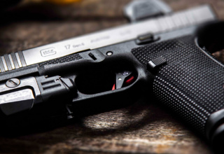
Three years ago, I had the pleasure of test driving one of the first Alpha Competition trigger systems that Timney Triggers developed for GLOCK pistols. Having tried my hand at other aftermarket systems and tweaks for this iconic handgun, the Alpha Competition proved to be a breed apart and a massive improvement over the original trigger.
In short, the Alpha Competition not only delivers a more simplified GLOCK trigger system, but it also refines the overall feel and performance by a substantial margin. The completely reimagined sear and trigger bar design provides a much crisper and more precise sear break than the factory unit. You pull back to the decisive wall and only a minor, ultra-smooth tug releases the firing pin. The reset is also exquisitely short. Combine that with Timney’s redesigned trigger return spring system and you have an enhanced trigger with competition-grade performance that will never be overtaxed by even the most competent and skilled shooters.
Timney, though, is all about delivering what their customers ask for. That’s why the Alpha Competition came to be — customers who enjoyed Timney triggers in their hunting and competition rifles wanted the same for their GLOCKs. But customers can be a demanding lot at times. With the Alpha Competition came cries for a Timney spin on GLOCK slide components to match. Now, Timney has answered that demand with the Ultimate Builder’s Kit for GLOCK for Gen 3/4 and Gen 5 GLOCKs with double-stack mags. The kit is not compatible with 10mm or .45 ACP models.
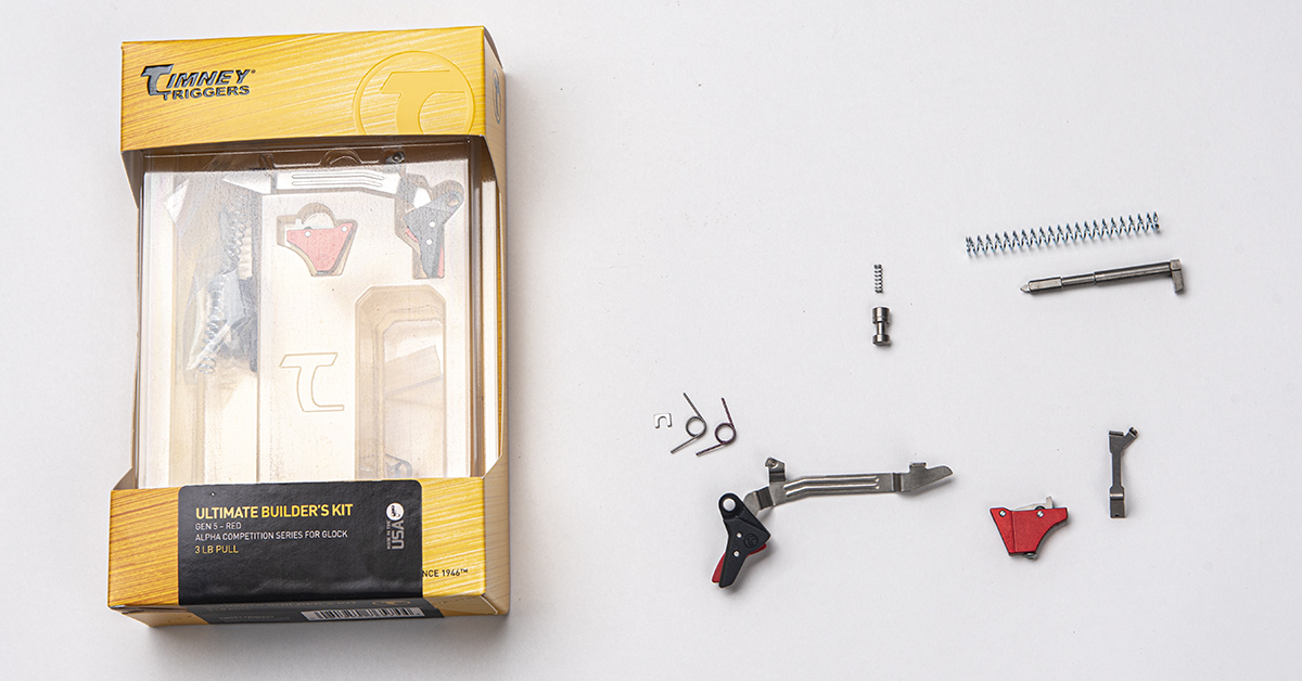
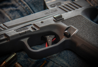
The Ultimate Builder’s Kit comes with all the interactive components of the GLOCK trigger and safety systems. The heart of the kit is the Alpha Competition trigger, which has also been slightly upgraded with the inclusion of a C-clip washer to enhance security and stability of the sear mechanism in the OE trigger housing. (On a side note, this C-clip can be easily added to the original Alpha Competition trigger for those who have already purchased one. Just contact Timney and they will send one to you free of charge. It is a good upgrade that we highly recommend.)
In addition to the trigger assembly, the Ultimate Builder’s Kit comes with a new connector (not present in the original Alpha Competition kit) along with two trigger return springs boasting different spring rates. The silver spring is the baseline spring that equates to the original reset spring tension. The heavier red spring offers a firmer, more positive reset that really helps the shooter keep “reset overtravel” to a minimum. That is the spring I installed on my G17 conversion, and I feel it offers better trigger control during fast-fire strings.
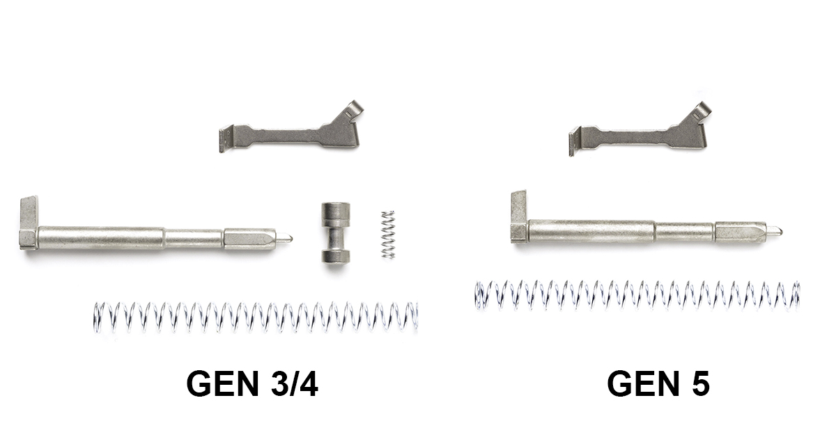
While the Alpha Competition trigger system works perfectly well with the factory slide assembly — specifically the firing pin and firing pin safety — customers wanted Timney to develop these components to match the Alpha Competition system in the expected Timney way. To that end, Timney has produced their own stainless steel firing pin and firing pin safety — items better tuned to the Alpha Competition’s trigger bar and sear geometry. This end of the kit for Gen 3 and 4 GLOCKS comes with a new firing pin, firing pin spring, firing pin safety, and firing pin safety spring. The Gen 5 kit comes with all the same components except for the firing pin safety and firing pin safety spring.
All key components in the kit are heat-treated and NP3 coated for enhanced durability and lubricity to ensure smooth operation.
While I can’t validate the performance benefits of the kit’s slide components simply because I’m not a skilled enough pistol shooter to detect such slight nuances, I can say that, overall, the Alpha Competition system offers a remarkable refinement to the GLOCK. The flat-face trigger shoe, elimination of the “mushy” stock trigger feel, the positive wall at the end of initial take-up, the crisp sear break, and the short, positive reset makes the upgraded GLOCK a fun shooter that promotes accuracy and speed.
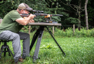
The trigger system is also lighter. After installing the Ultimate Builder’s Kit on my G17, I tested the trigger pull with a Lyman scale. One ten-pull average revealed 2 lbs., 0.1 oz. The second round of ten pulls averaged 1 lb., 11.5 oz. That is consistent. I’ll call it a 2-lb. trigger. Timney states that the system is set at the factory for 2.5-3 lbs.
Whatever the case, the trigger feels great and is a light year’s improvement over the factory system.
Installing the Ultimate Builder’s Kit
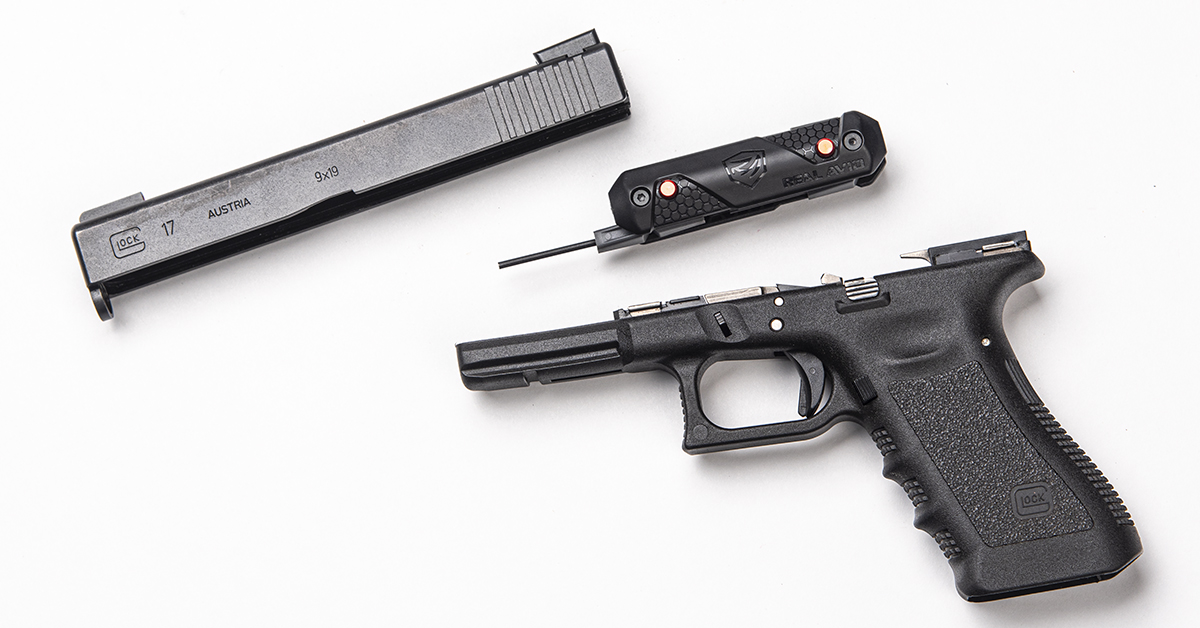
All components relative to Timney’s GLOCK conversion can, in theory, be removed and installed with only a punch or GLOCK tool. In reality, you may want a bench block and a punch/hammer set on hand, as the trigger pin can sometimes require a firm tap or two to move through the components. For this project, we leaned heavily on Real Avid’s 4-in-1 Tool for GLOCK. This tool comes with the required punch, as well as a front sight removal tool, Allen wrench, and flat-blade screwdriver.
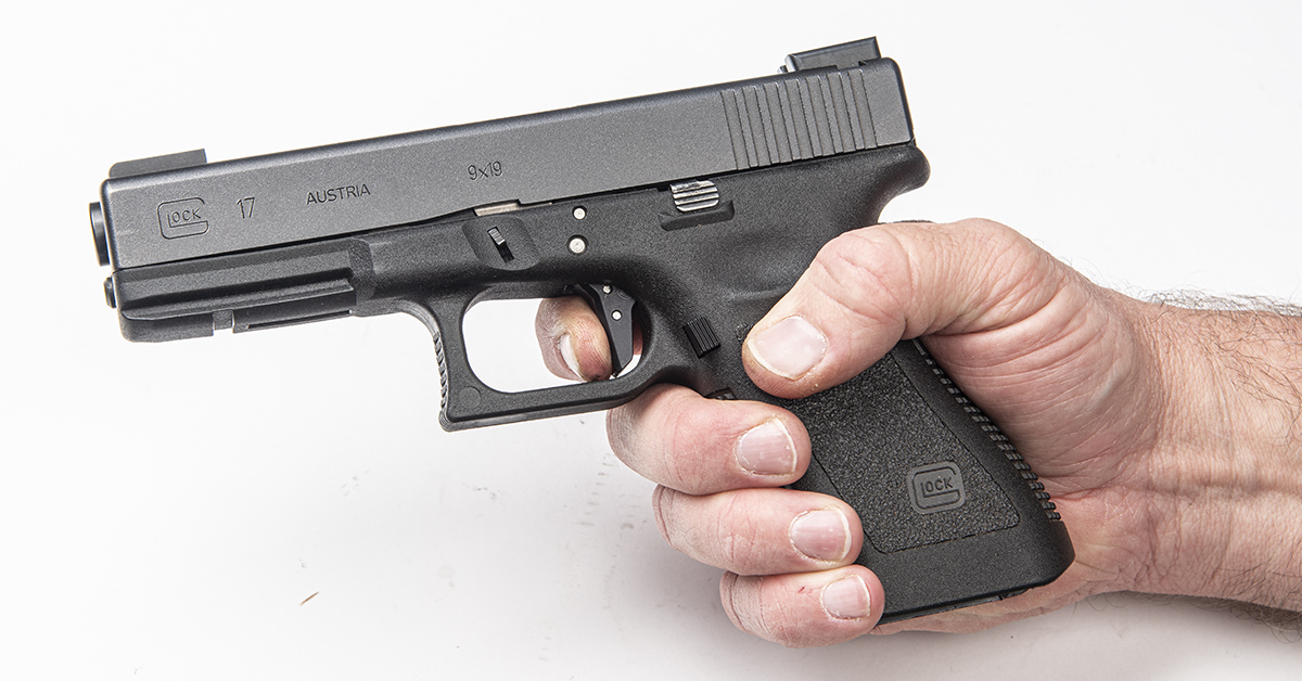
Begin by removing the magazine and rendering the firearm safe (no cartridge in the chamber). Disassemble the pistol by removing the slide from the frame and the barrel and the guide rod and recoil spring assembly from the slide.
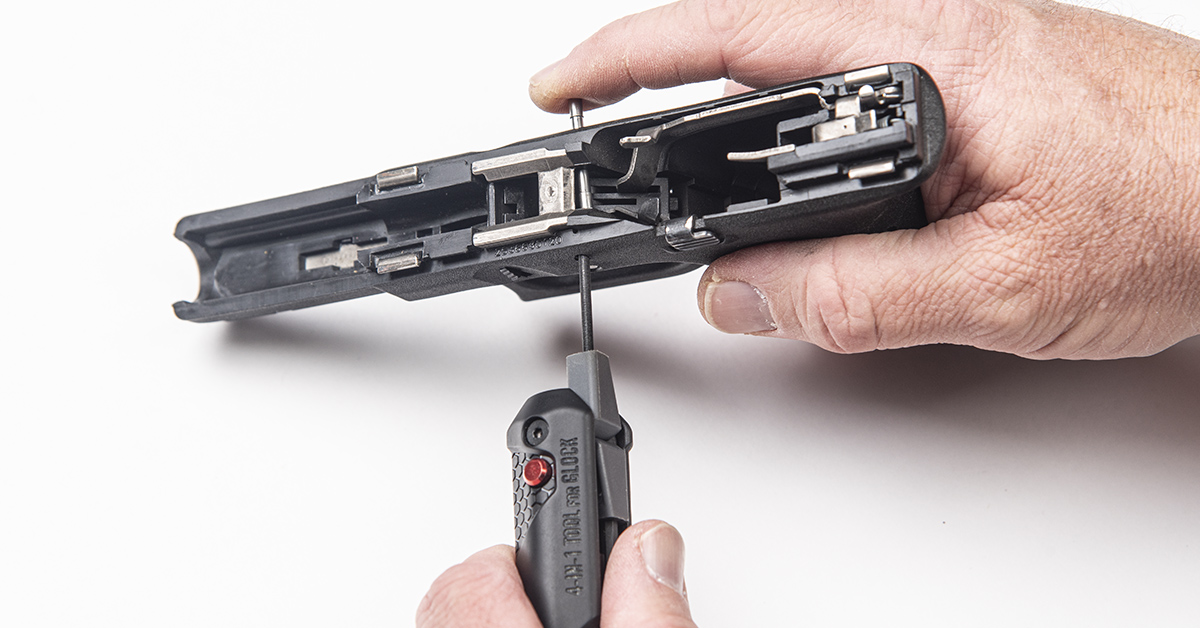
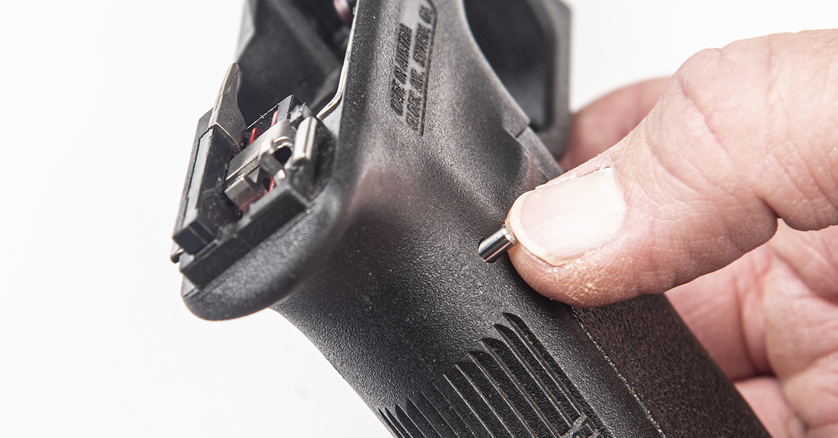
Push out the locking block pin from left to right.
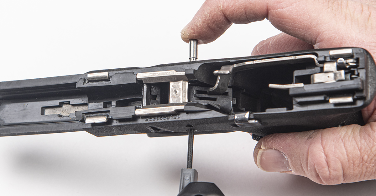
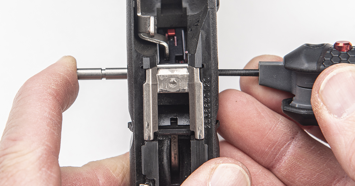
Push out the trigger pin from left to right.
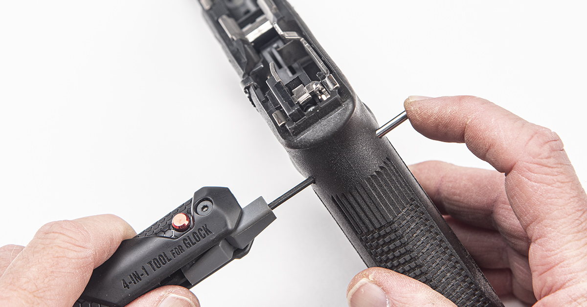
Push out the trigger housing pin from left to right.
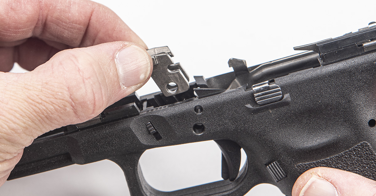
Lift out the locking block. You may need to use a small, flathead screwdriver to pry it loose from the frame.
Lift out the slide stop lever and spring assembly.
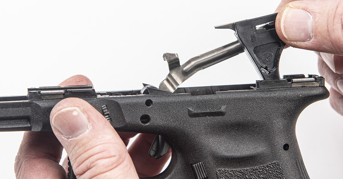
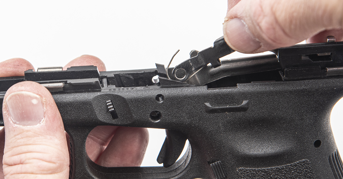
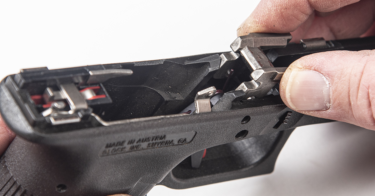
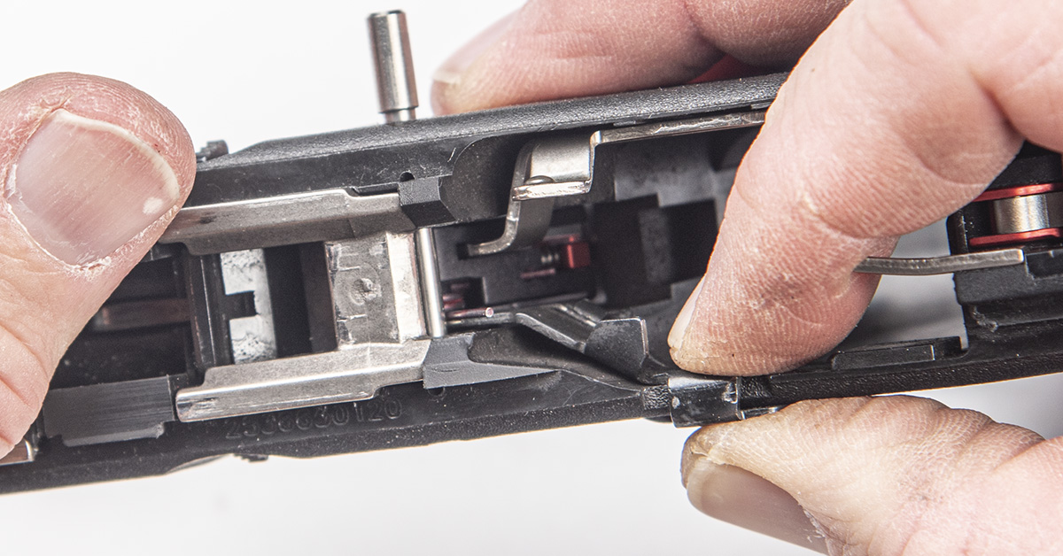
The trigger and trigger housing assembly can now be lifted out of the frame.
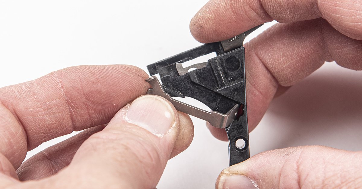
Twist and rotate the trigger bar cruciform out of its slot in the trigger housing.
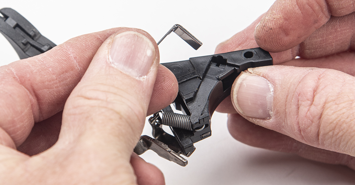
Pry the connector out of the trigger housing.
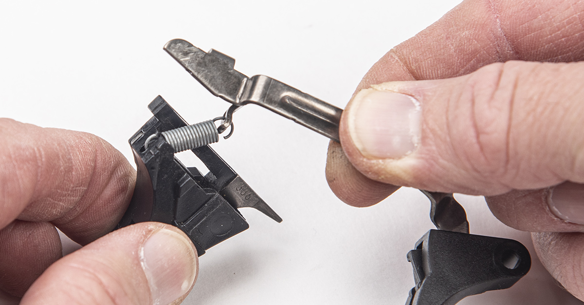
The trigger spring connects the trigger housing to the trigger bar. Unhook the trigger housing from the spring. The trigger spring and trigger bar assembly will not be used.
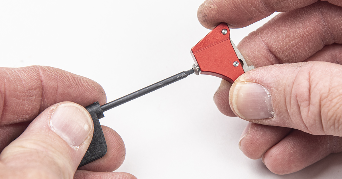
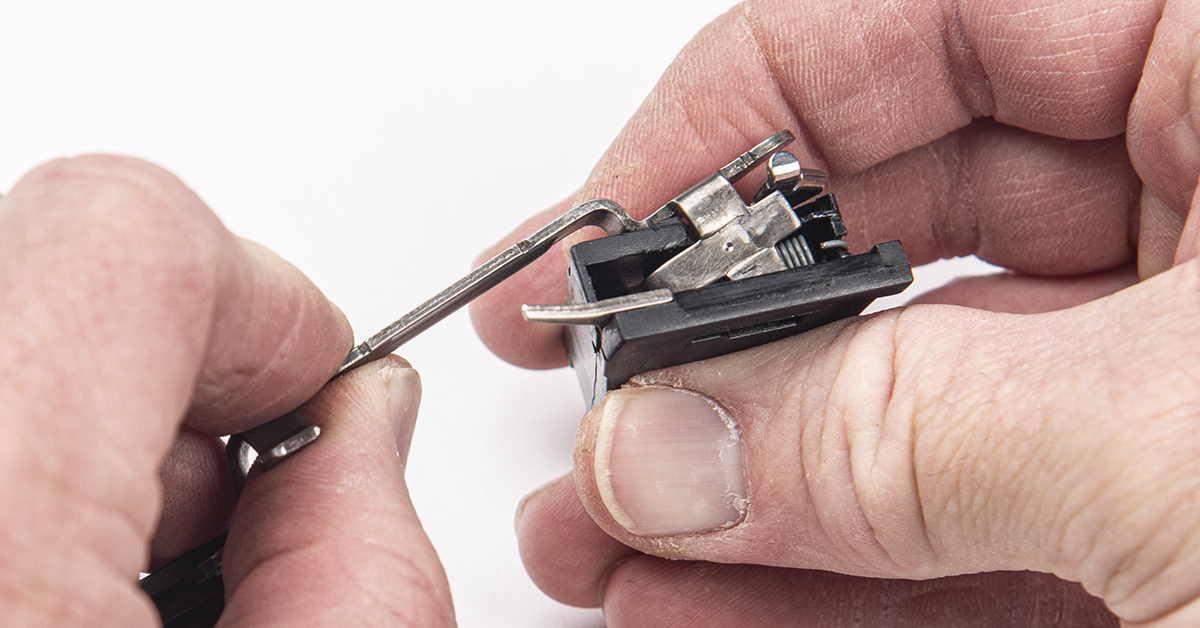
Using the wrench supplied with the Ultimate Builder’s Kit, back the buttonhead retaining screw about halfway out of the sear mechanism.
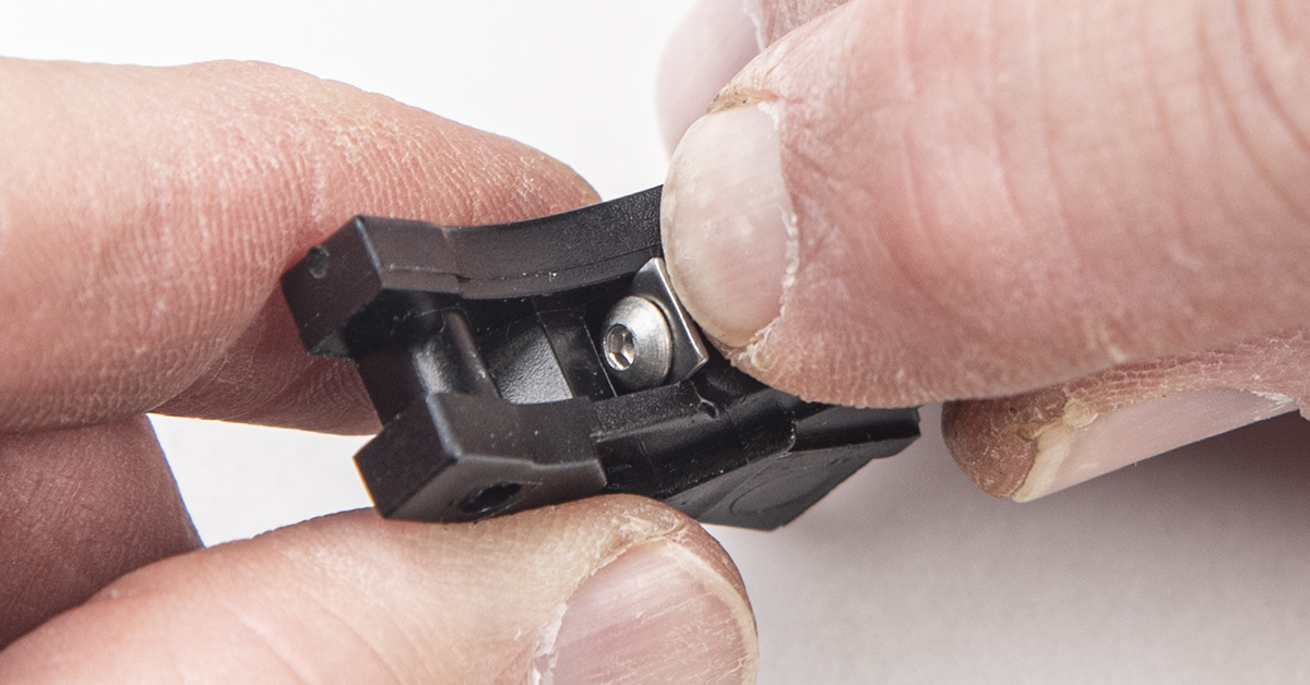
Insert the sear mechanism firmly into the trigger housing and place the C-clip washer between the screw head and the housing. Be sure to push the C-clip all the way into position.
Tighten the retaining screw.
Install the new connector into the trigger housing. Make sure the connector is firmly seated.
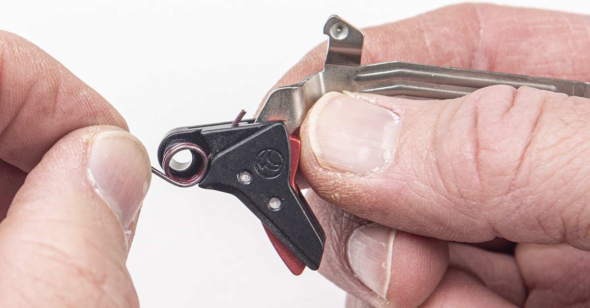
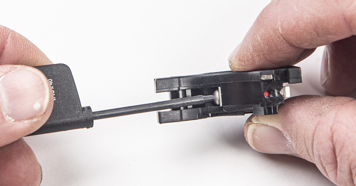
Moving to the trigger assembly, select your preferred trigger reset spring. Again, silver for “normal” and red for a firmer, more positive reset feel. Insert the inside leg of the pin through its hole in the trigger, as shown, and snap the coil over the trigger pin hole boss.
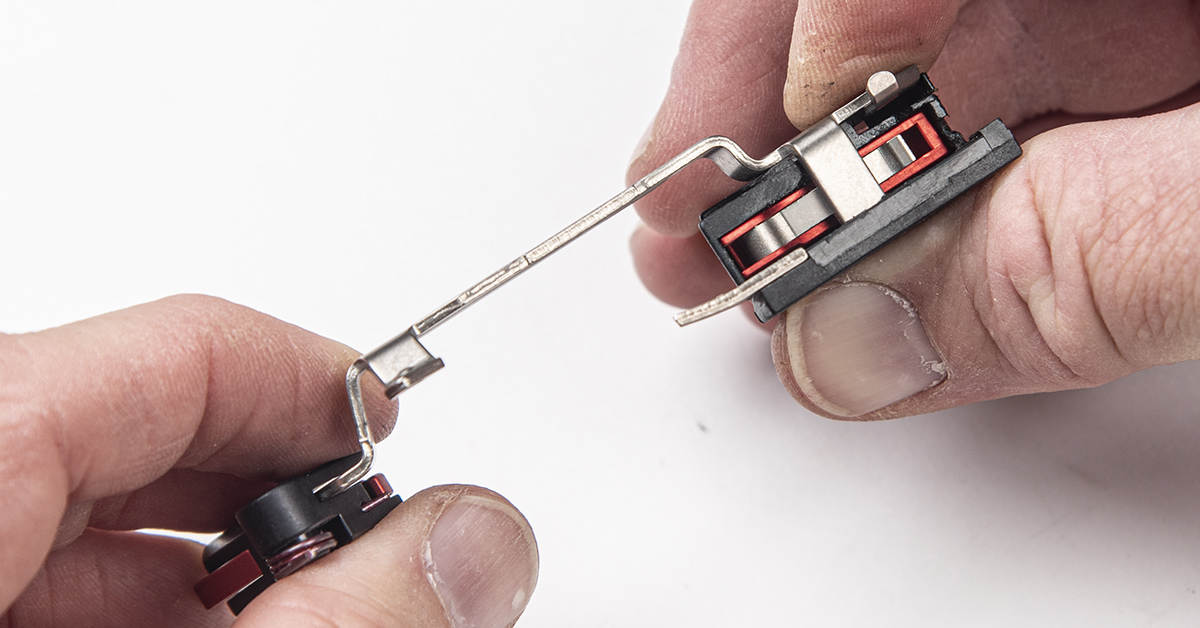
Install the trigger bar into the trigger housing, making sure the crossbar fits into its slot on the left side of the housing.
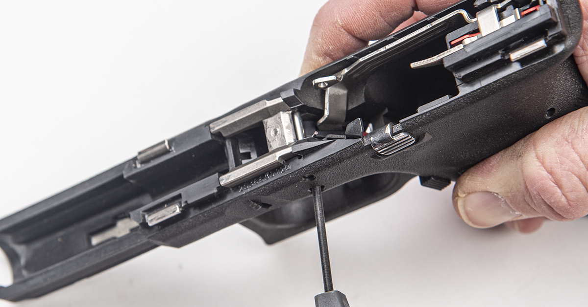
You can now drop the trigger assembly into its position in the frame.
Insert the trigger housing pin from right to left. Ensure that the pin is centered in the frame.
Install the locking block into its position in the frame.
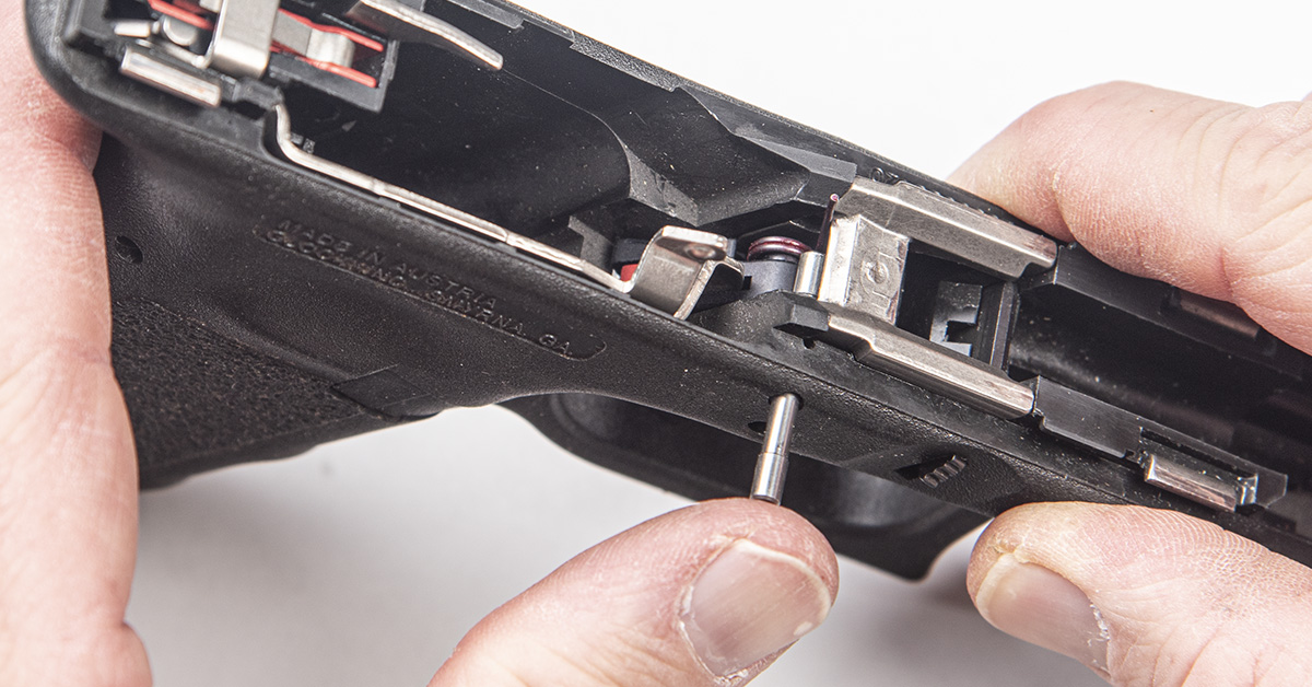
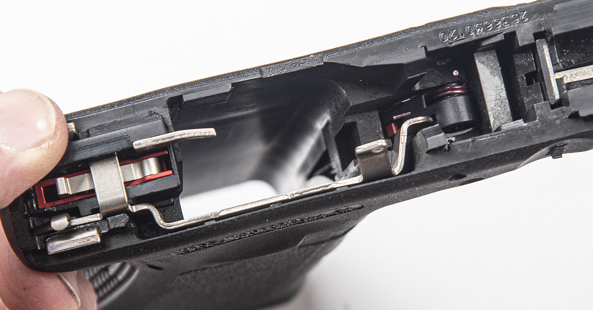
Install the locking block pin halfway through the frame assembly. Note that the outer leg of the trigger return spring is blocking passage of the pin.
Use a fingernail or small flathead screwdriver to move the spring leg back to provide clearance for the locking block pin, and then push the pin the rest of the way into the frame, making sure it is centered.
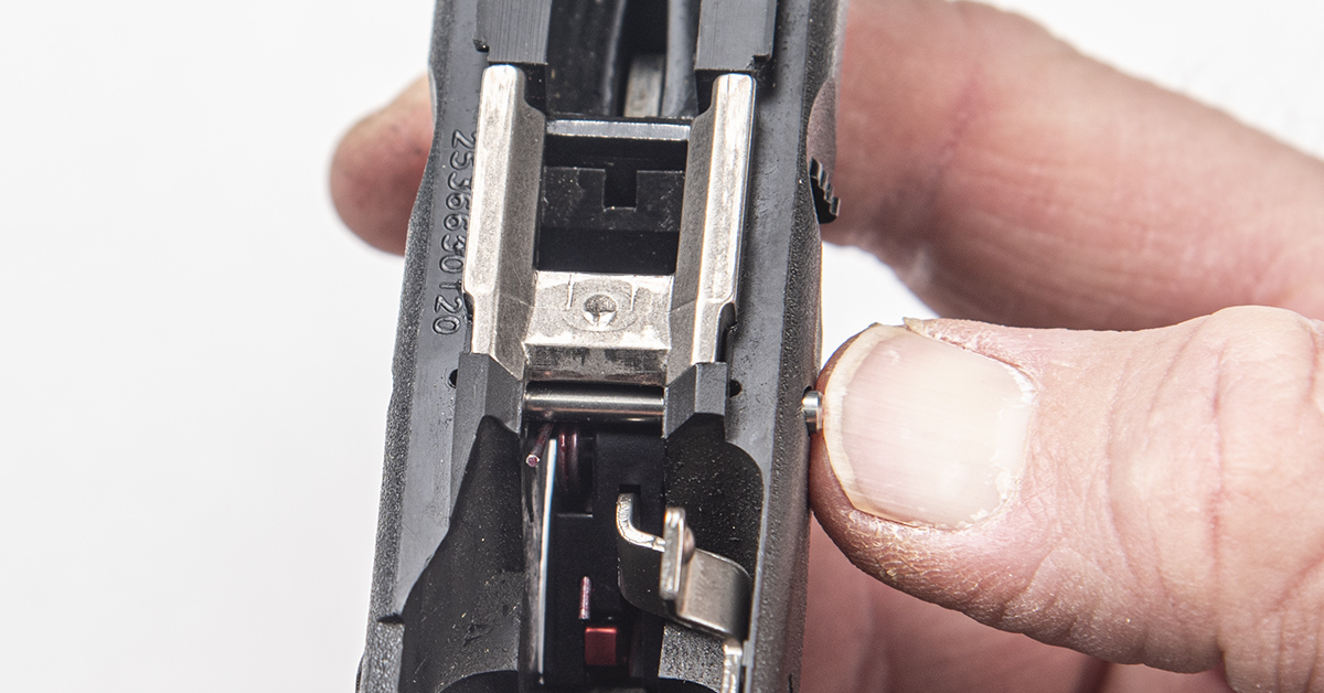
Install the trigger pin halfway into the frame. Here, you may want to use your punch as a slave pin to align the pin holes. Note that the pin is being installed from the right side of the frame to the left.
Reinstall the slide stop lever and spring assembly into the frame.
Use the punch as a slave pin to align the trigger and slide stop lever holes, and then push the pin into place, making sure it is evenly positioned in the frame.
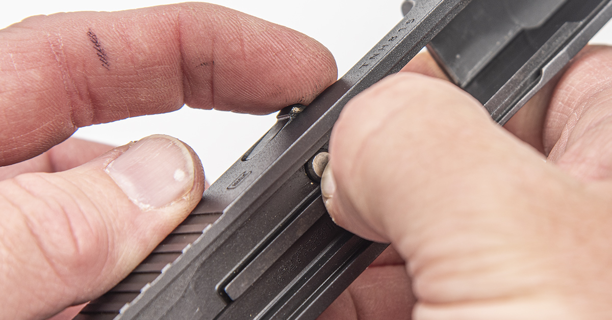
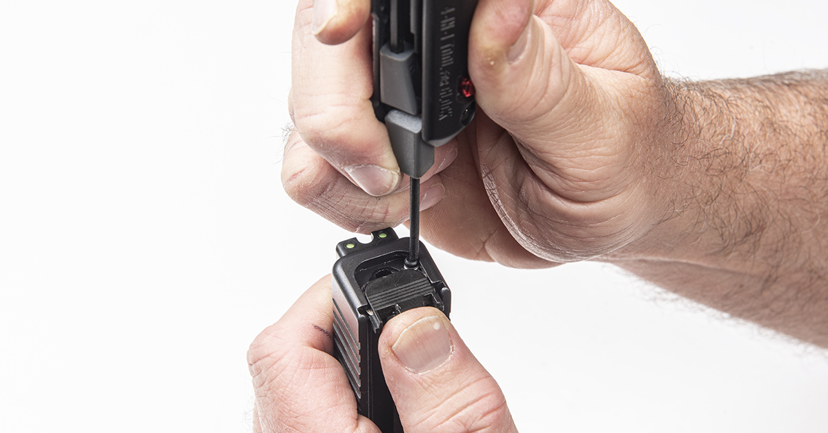
Installation of the new slide components requires removal of the slide cover plate. The plate is held in place by the tension created against it by the firing pin spring spacer and the extractor depressor plunger spring bearing.
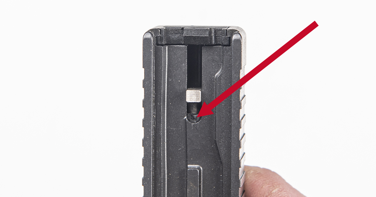
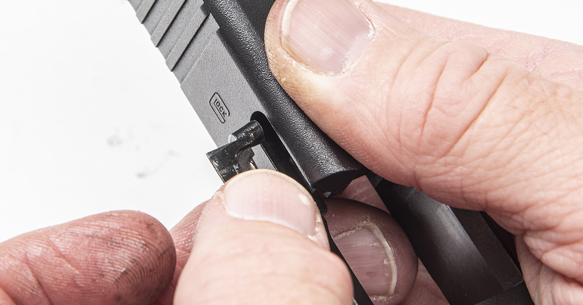
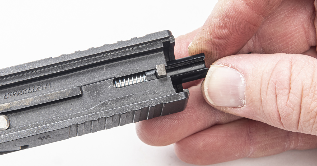
Removal of the slide cover plate also requires the firing pin spacer sleeve (arrow) to be pushed forward so that the cover plate can be slid down and off the slide. Before you do this, you must take precautions!
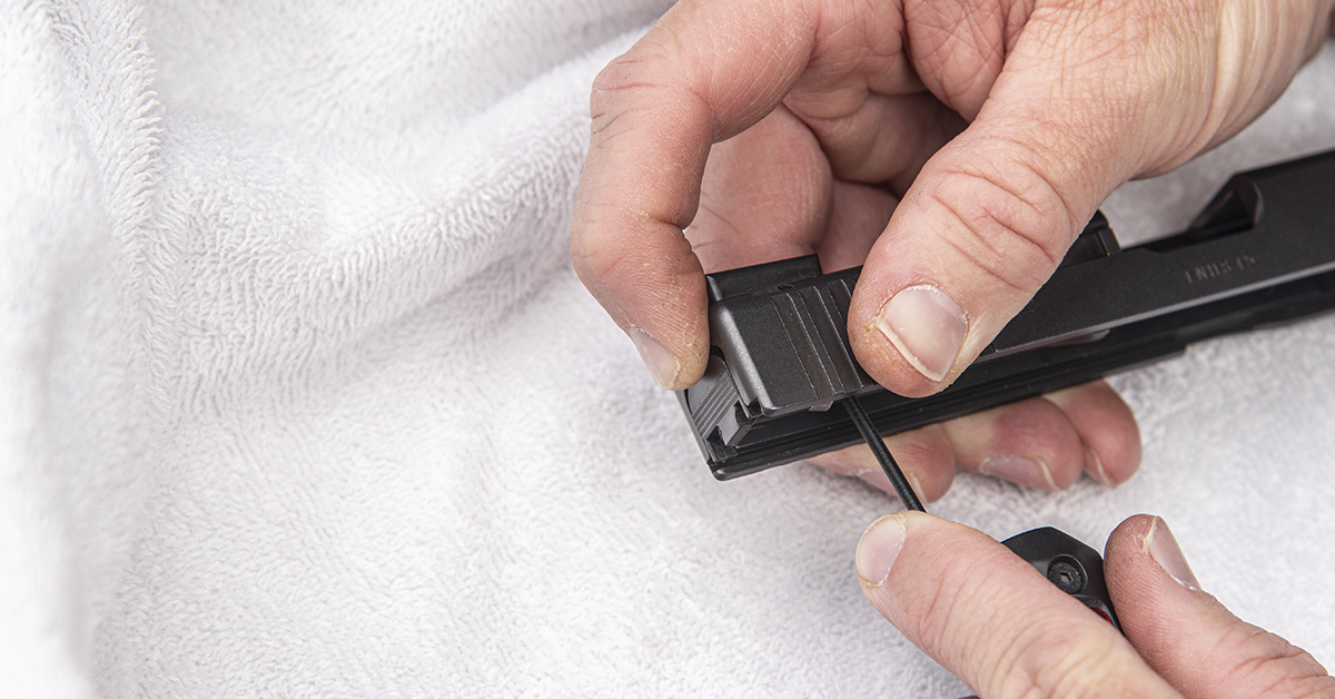
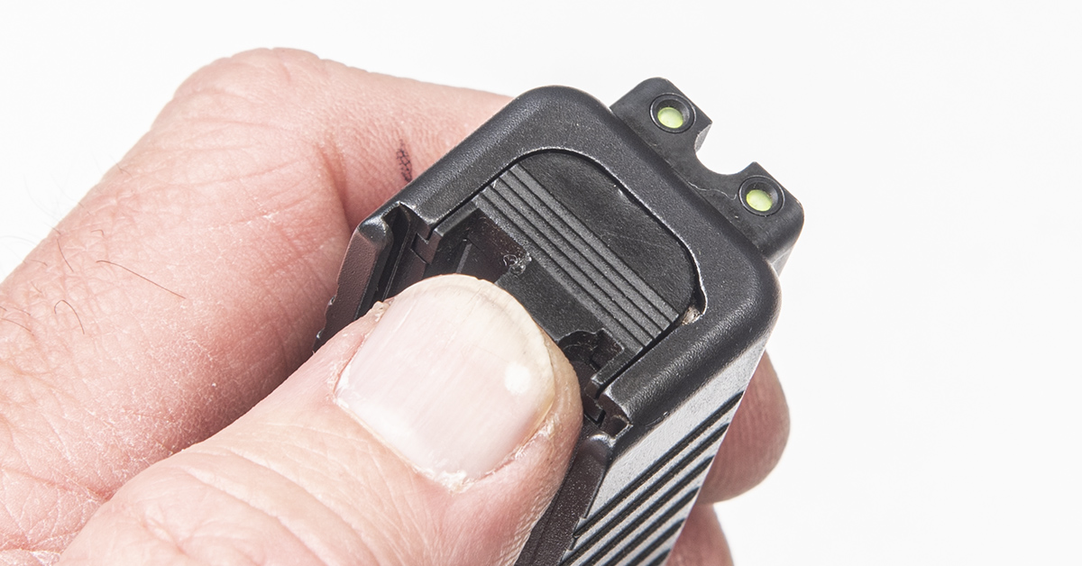
The extractor depressor plunger behind the slide cover plate is under considerable spring tension and the spring will launch across the room (possibly never to be found) if it is not captured as the plate moves off the slide. To prevent this, I recommend using a towel as a backstop as you push the firing pin spacer forward and the cover plate downward. This way, if the spring launches, the towel will absorb the impact and keep you from losing the spring.
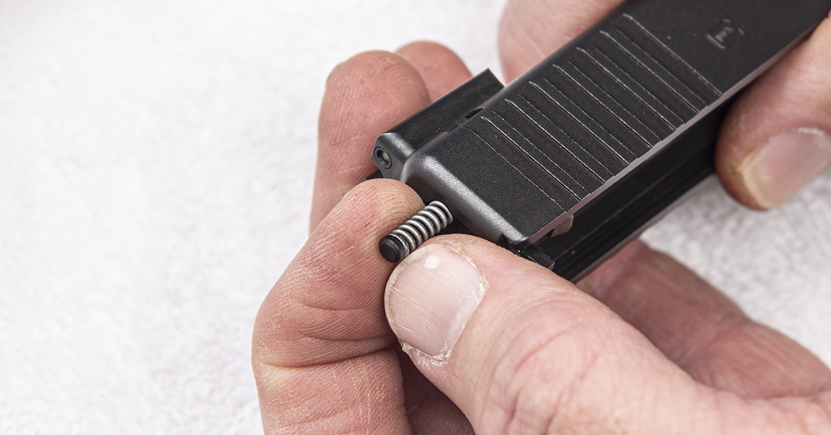
If you successfully captured the extractor depressor plunger spring as you removed the cover plate, pull the spring from the slide.
With the spring removed, the extractor depressor plunger can be removed from the slide.
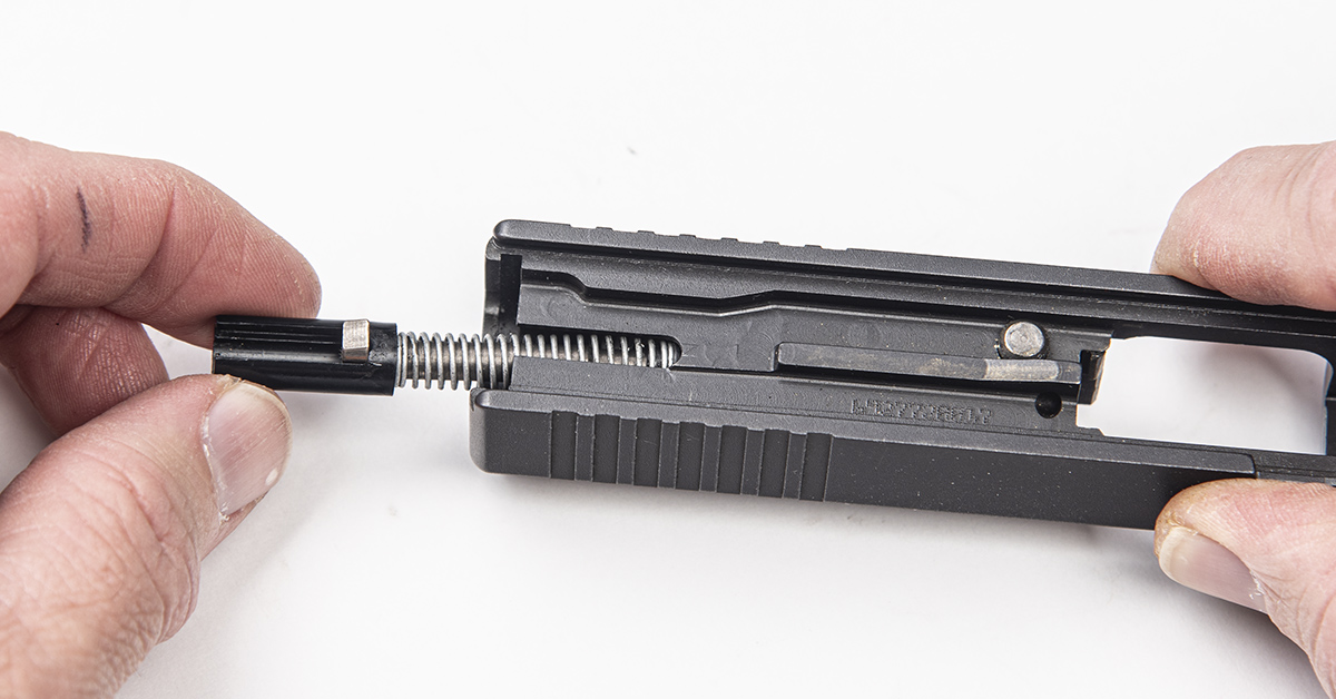
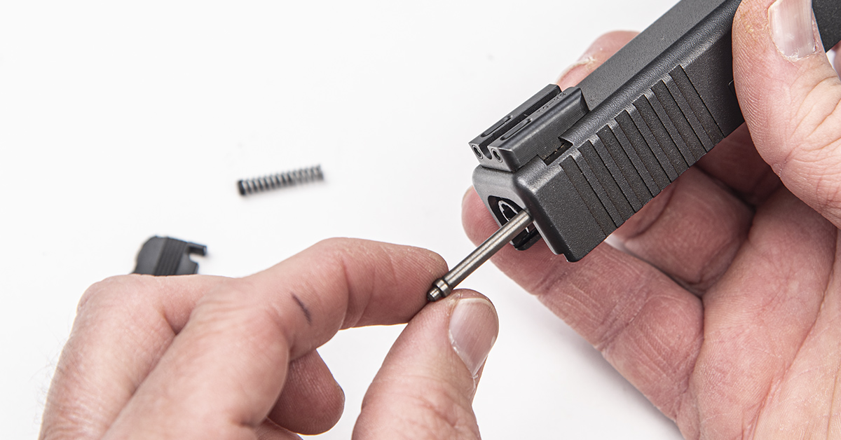
Remove the firing pin spacer and firing pin/spring assembly from the slide.
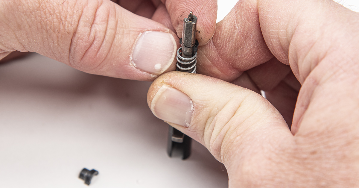
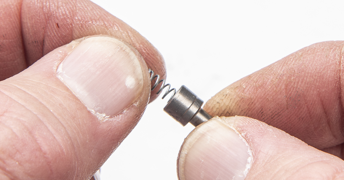
The OE firing pin spacer and spring cup halves must be used for the new firing pin assembly. To remove the spring cups halves, place the assembly upright, as shown, and depress the spring with one hand while removing the cup halves with the other. Be sure to maintain control of the spring to prevent it from launching across the room. With the spring cup halves removed, separate the spring, firing pin, and firing pin spacer.
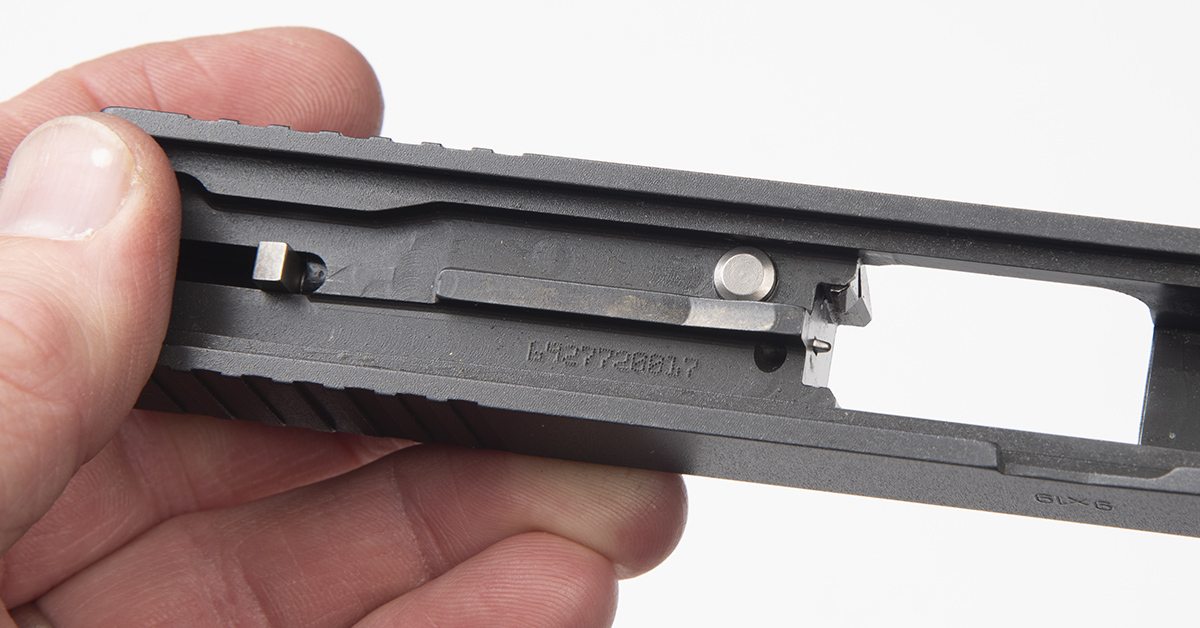
With the extractor depressor plunger assembly removed, the extractor and firing pin safety assembly can be removed from the slide. Do this by depressing the firing pin safety until the extractor can be lifted out or dropped out of the slide.
Remove the firing pin safety assembly from the slide.
Lightly grease the bottom of the new Timney firing pin safety and install the spring into the safety’s spring pocket.
Lightly grease the inner surface of the extractor. Install the firing pin safety and spring into the slide and depress the safety while inserting the extractor into the slide. Release the safety. The spring creates tension between the safety and extractor to keep both components in place.
Lightly grease the back portion of the new Timney firing pin and install the pin in the spacer sleeve.
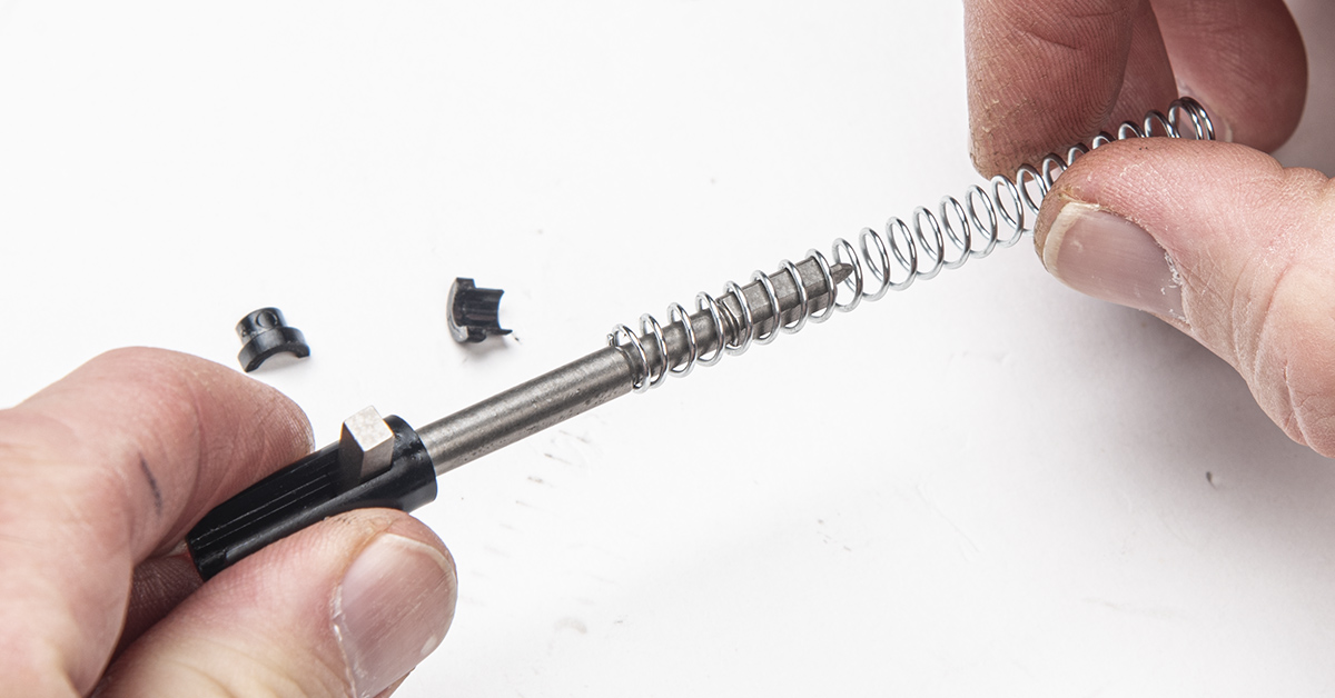
Lightly grease the firing pin spring and install it onto the firing pin.
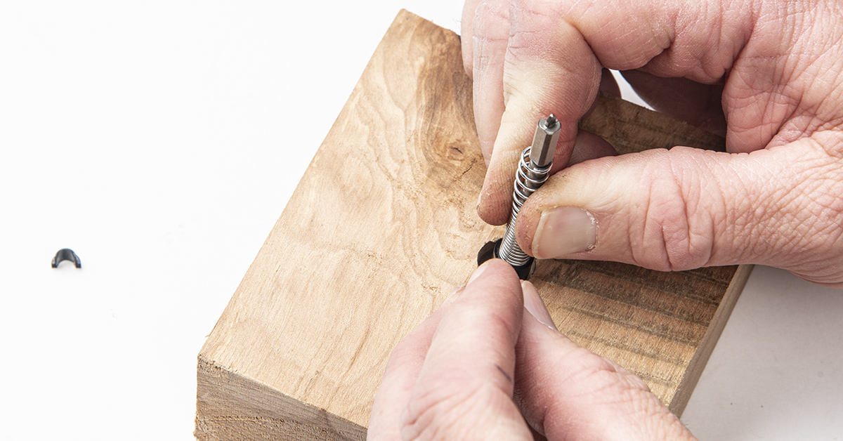
A wooden bench block works well for installing the spring cups. Catch the firing pin lug onto the edge of the block and depress the spring until you can insert the first spring cup half between the spring and the firing pin shoulder. Repeat for the other spring half. Be sure the spring cup joint does not align with the end of the firing pin spring coil.
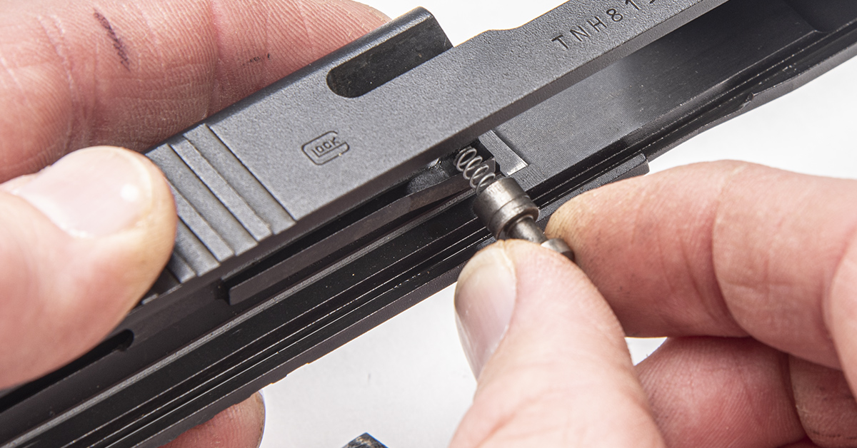
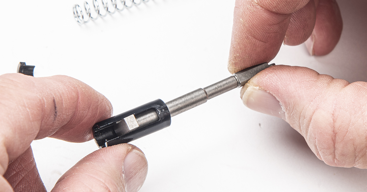
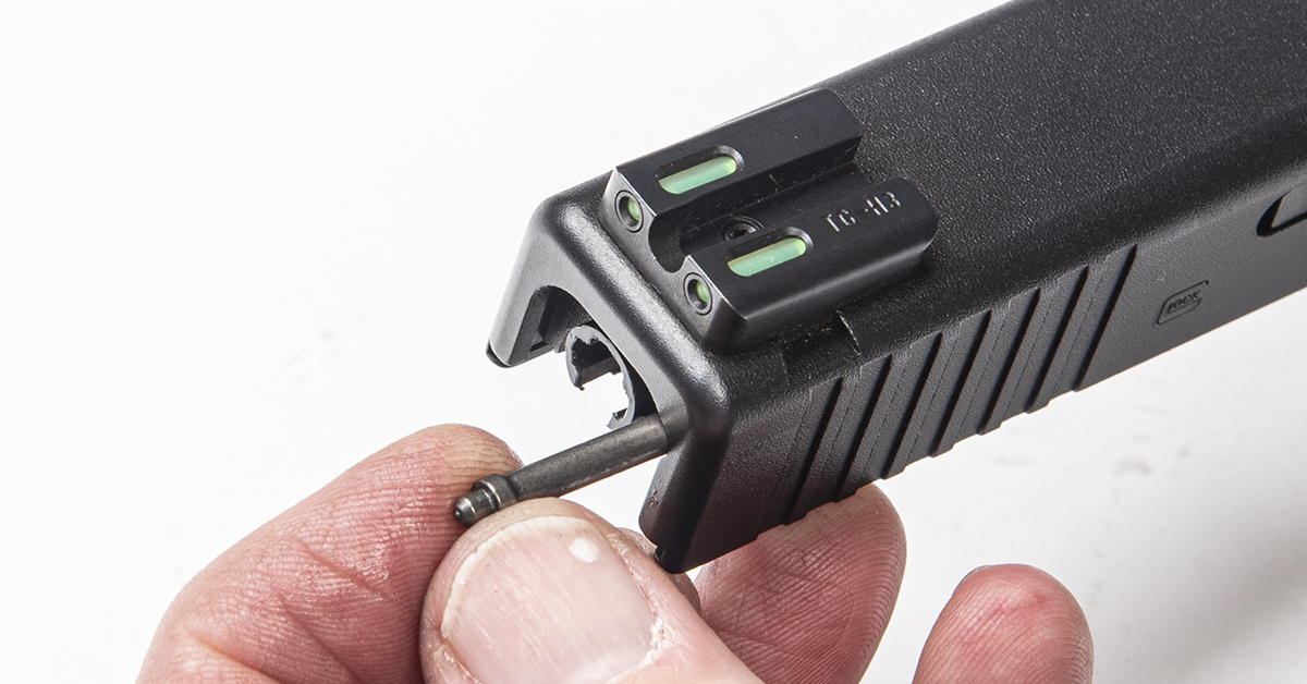
Insert the firing pin assembly into the slide as shown.
Lightly grease the extractor depressor plunger shaft and insert it in this orientation into its hole in the slide.
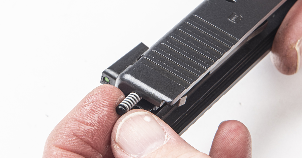
Lightly grease the extractor depressor plunger spring and insert it into the slide behind the plunger shaft with the spring bearing oriented toward the back of the slide, as shown.
Set the slide onto a solid surface and begin inserting the slide cover plate into its channels in the back of the slide. Press on the back of the firing pin spacer and move the cover plate until it captures the spacer. Next, use the punch to press against the extractor depressor plunger spring bearing while simultaneously pushing the cover plate into position, capturing the extractor depressor plunger assembly. BE CAREFUL HERE! If the punch were to slip before the extractor depressor plunger assembly is captured by the cover plate, the spring will launch out of the slide. Wear eye protection when performing this operation.
Push the cover plate firmly into its final position in the slide.
Test that the firing pin safety is working by depressing the safety while the slide is pointed muzzle-down. The firing pin should move freely in its channel and the tip should protrude through its hole in the breech face. Push back on the firing pin lug to return the firing pin to its safe, “at ready” position.
Complete the project by performing a function check of the assembled pistol. Cock the gun and pull back on the trigger without depressing the safety blade. The trigger should not move reward. Pull back on the trigger while depressing the safety blade. The firing pin should release. While maintaining the trigger in its rearward position, pull back and then release the slide to simulate a round fired. Slowly allow the trigger to move forward. You should here and feel the reset.
Upgrade Parts Also Available
Have already installed an Alpha Competition in your GLOCK and would like to add the Timney slide components and connector to the mix? No problem. Anticipating this need, Timney also offers the Ultimate Parts Kit for Gen 3/4 and Gen 5 GLOCKS with the Alpha Competition already installed. Each kit includes a connector, firing pin, and spring. The Gen 3/4 kit also comes with the firing pin safety and spring. Also…remember to request the free sear mechanism C-clip if you already installed an Alpha Competition trigger.